Although it is common practice to use a motion extraction program to extract the motion of an installed robot and then conduct a collision risk analysis, SafetyDesigner provides a motion creation feature for users who are in the midst of robot process design or who wish to verify robot safety before installation.
 Some robots may not be able to use the motion creation (Hand guiding) feature, depending on the development status.
Let’s look at the example below to see how to create motion.
1. Set default Position
After opening the motion settings menu, click the Home Position button to return the robot’s TCP to its original position.
Click Base or World to change how the X, Y and Z coordinate values of the TCP position are output. It is intuitive to proceed with motion creation checked on Base, since the settings for the robot’s position and robot stand are usually completed before motion creation.
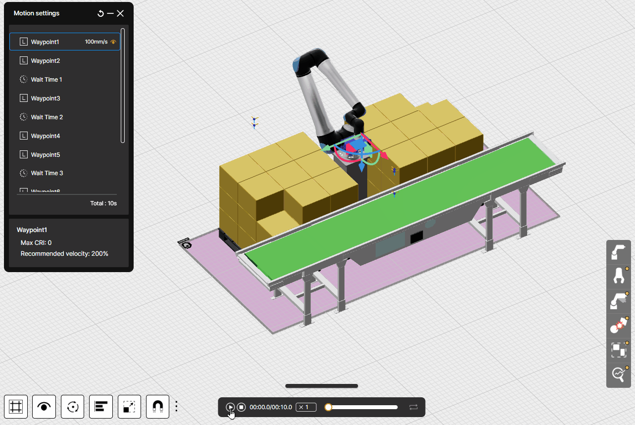
2. Create Waypoint
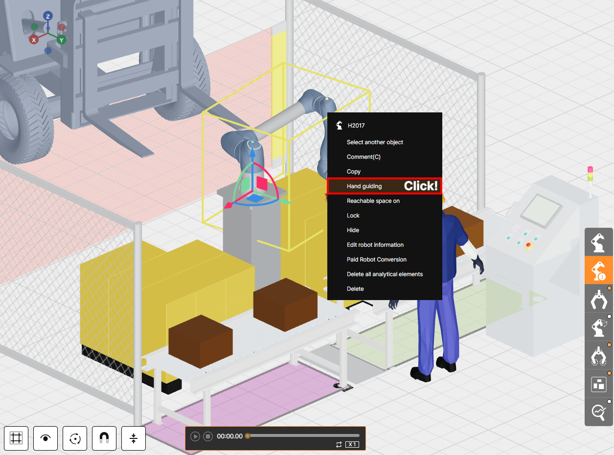
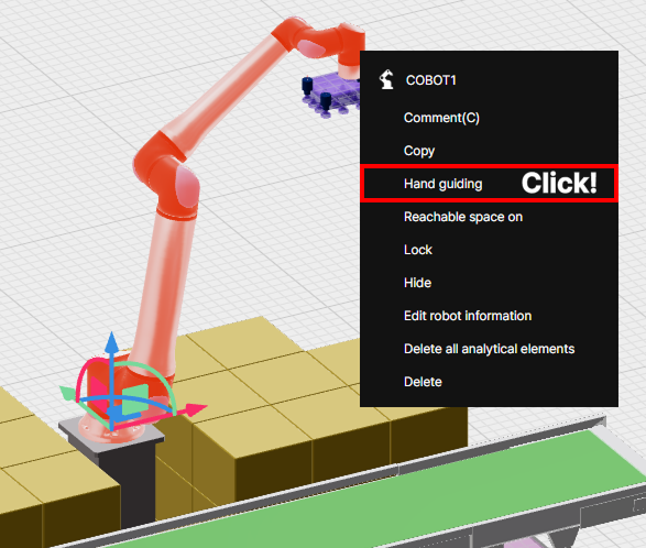
Create a Waypoint by entering the joint angle value or by moving the robot to the desired location on the 3D screen using hand guiding mode. In the tips below, explain how to create Waypoint using hand-guiding mode.
Right-click the robot and click Hand Guiding to change it to enable hand-guiding.
After enabling hand guiding, move the robot to the desired point on the 3D screen, and click Create waypoint button to specify multiple waypoint. If necessary, you can create waypoint by changing the Move mode to Move L or Move J.
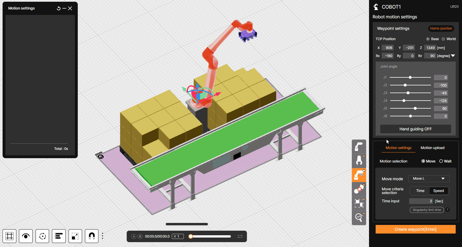
Move modes have the following characteristics.
– Move J(Joint): Robot’s joint angle controls precise positioning, but unnecessary movements can occur, such as moving in curves.
– Move L(Linear): Robot moves in a straight way and can specify an accurate path, but cannot control the robot’s joint angle for a specific location.
Once you’ve completed creating waypoints, check the layer on the left side of the 3D screen to verify the waypoints have been successfully generated.
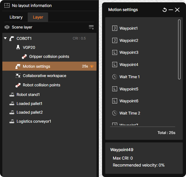
You can set up up to 50 waypoints.
To adjust motion settings (such as speed or move mode) for the path from one Waypoint to the next, edit the settings of the destination Waypoint, not the starting Waypoint. For example, to modify the speed or move mode for the travel from Waypoint1 to Waypoint2, change the settings for Waypoint2, not for Waypoint1.
3. Modify motion speed or motion time
Change the speed to the speed to be applied to the actual application or enter the estimated travel time between waypoints.
Let’s learn about two different ways to modify motion speed.
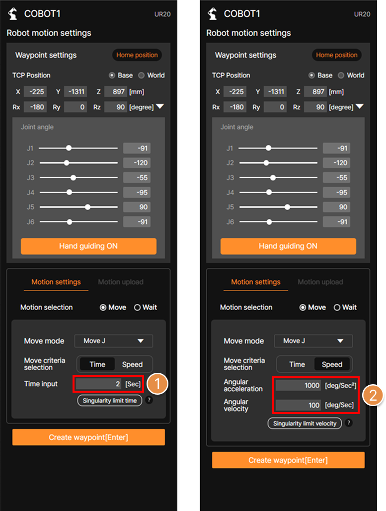
① Time setting
You can adjust the speed of motion by setting the travel time between waypoints. Select the waypoint you want to adjust the speed in the layer window on the left side of the 3D screen, then click the Time setting tab to enter the desired time.
② Velocity setting
Select the Waypoint you want to adjust the speed in the layer window on the left side of the 3D screen, then click the Velocity setting tab to input the (angular)acceleration and (angular)velocity value.
If the selected Waypoint is in Move L mode, enter the desired velocity and acceleration value, and if it is in Move J mode, enter the desired angular velocity and angular acceleration value, which is immediately corrected.
③ Singularity limit time / Singularity limit velocity
![]()
Singularity in a multi-joint robot refers to a condition where the robot’s joints or TCP(Tool Center Point) reach a specific position or orientation, causing the movement to become abnormal or unpredictable.
In SafetyDesigner, you can create robot motion that moves at maximum speed while avoiding singularity. According to the settings of each Waypoint, you can use the function by clicking the desired button for Singularity limit time or Singularity limit velocity.
4. Verify created motion
After completing the waypoint settings and adjusting the motion speed, press Play button at the bottom of the 3D screen to verify that the motion has been generated successfully.