
- 1. Safety Spaces of Robot Systems
- 2. Documenting Safety Space Information for Robot Systems
- 3. Calculating Safety Distances for Robot Systems
To safely operate industrial robot systems, including collaborative robots, it is essential to clearly define specific spaces during system setup. These defined spaces serve as the foundation for conducting a thorough risk assessment. Furthermore, when installing safety sensors such as radar sensors, 2D laser scanners, light curtains, or safety mats within the robot system, clear guidelines must be followed for calculating the required safety distances.
This section explains the names and types of safety spaces, as well as methods for calculating safety distances based on relevant standards.
1. Safety Spaces of Robot Systems

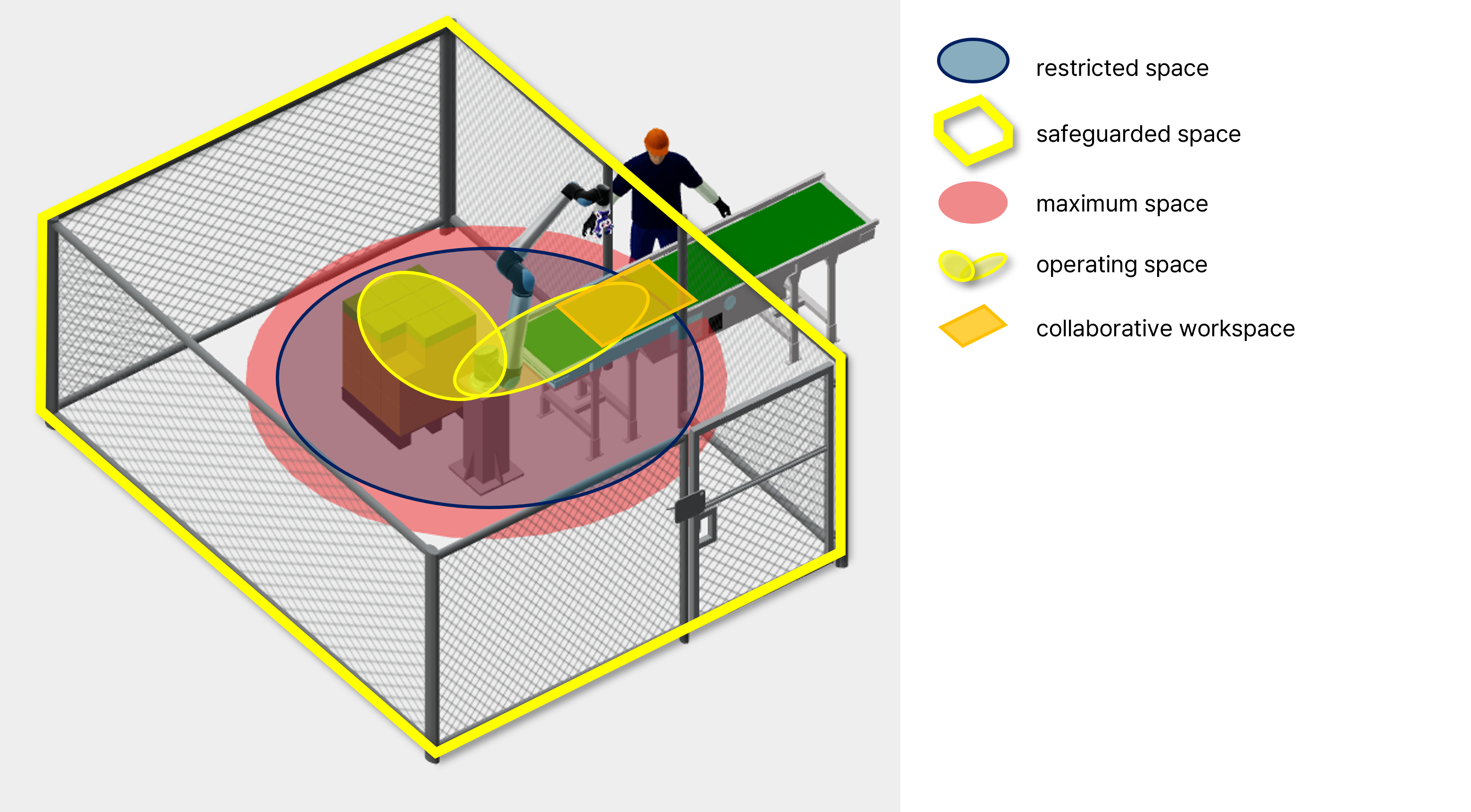
① Restricted Space

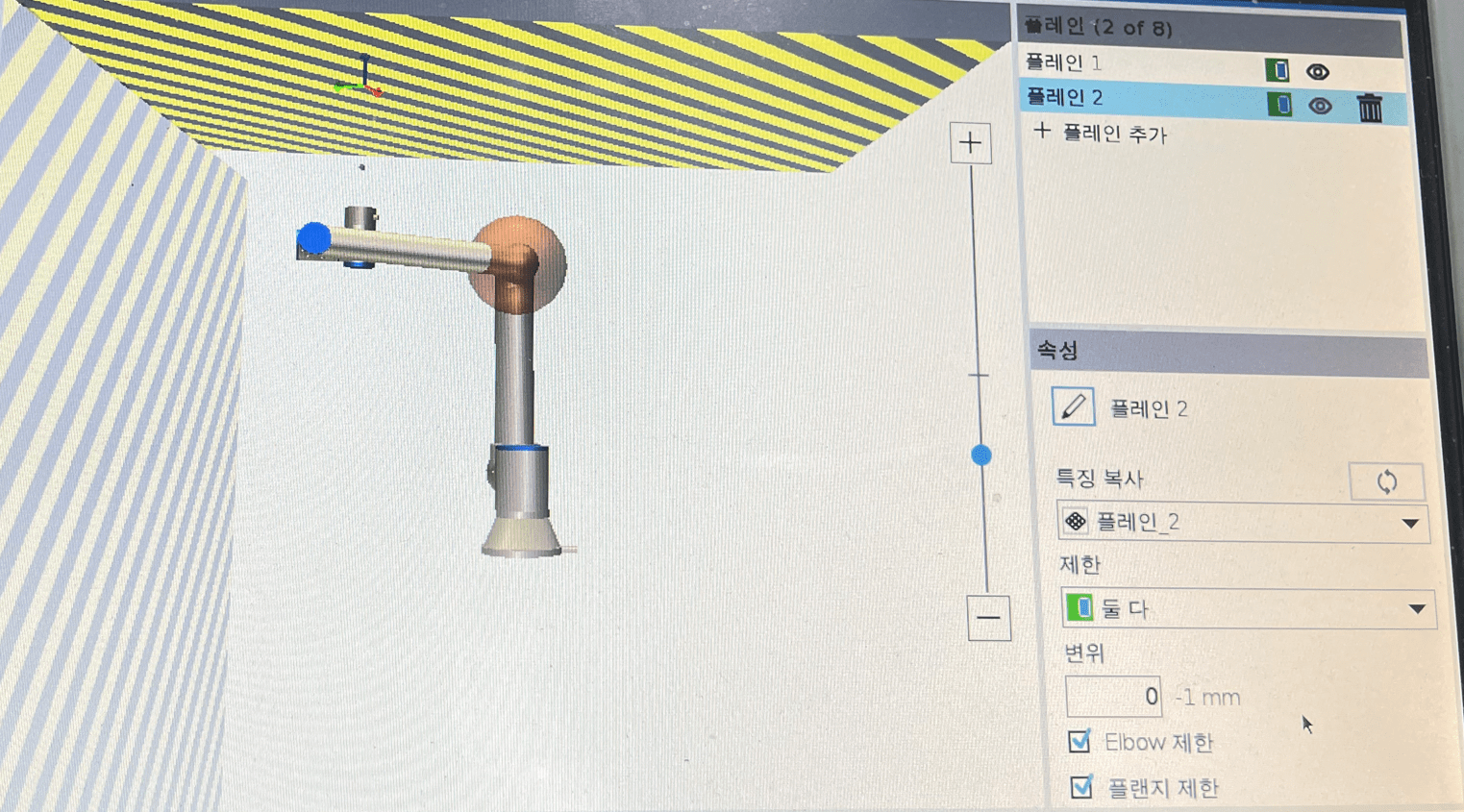
Collaborative robots generally have a safety rating of PL d, Category 3, enabling users to set software-based restricted spaces through safety functions provided by the manufacturer via the teaching pendant. If the robot moves beyond these restricted spaces, it automatically enters a protective stop state.
For robots that cannot support software-based restriction of spaces, physical measures such as mechanical stoppers can be used instead.
② Safeguarded Space
Safeguarded space refers to a defined space where human access is physically restricted by safety fences or when human presence is detected by safety sensors such as radar sensors, 2D laser scanners, light curtains, or safety mats.
The safeguarded space typically includes the restricted space and operating space.
③ Maximum Space
Maximum space is the area covering all points that the robot can physically reach, including the robot itself, its end effector, and any workpiece moved by the robot.
④ Operating Space
Operating space is the portion of the maximum space where the robot, including its end effector and any handled workpiece, performs tasks according to user-defined operational programs.
⑤ Collaborative Workspace
Collaborative workspace is the portion of the operating space where the robot and human workers can be present simultaneously or sequentially, allowing direct interaction and cooperation.
⑥ Deceleration & Stopping Space
Deceleration & Stopping space is the region where safety sensor triggers cause the robot to decelerate or stop.
2. Documenting Safety Space Information for Robot Systems
During the risk assessment process for industrial robot systems, you must document the safety space information.
Although there is no mandatory format for risk assessment documentation, this page explains how to generate risk assessment reports using the risk assessment feature provided in SafetyDesigner.
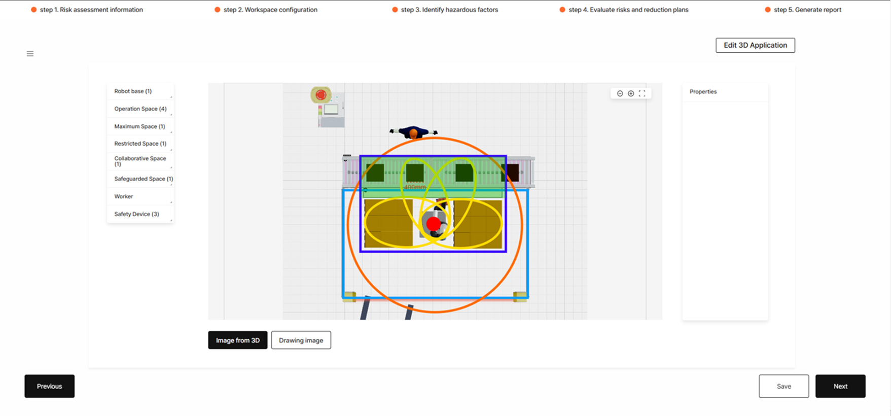
Enter the information about safety spaces configured in the robot system into the risk assessment report. When entering this information, clearly specify distances by providing either the drawing scale or approximate distances between pieces of equipment.
After entering the safety space and distance information, indicate the locations of workers and safety devices in the robot system (e.g., emergency stop buttons, sensitive protective equipment, and tower lamps).
SafetyDesigner’s workspace configuration feature allows you to quickly and easily enter safety space information using a drag-and-drop interface.
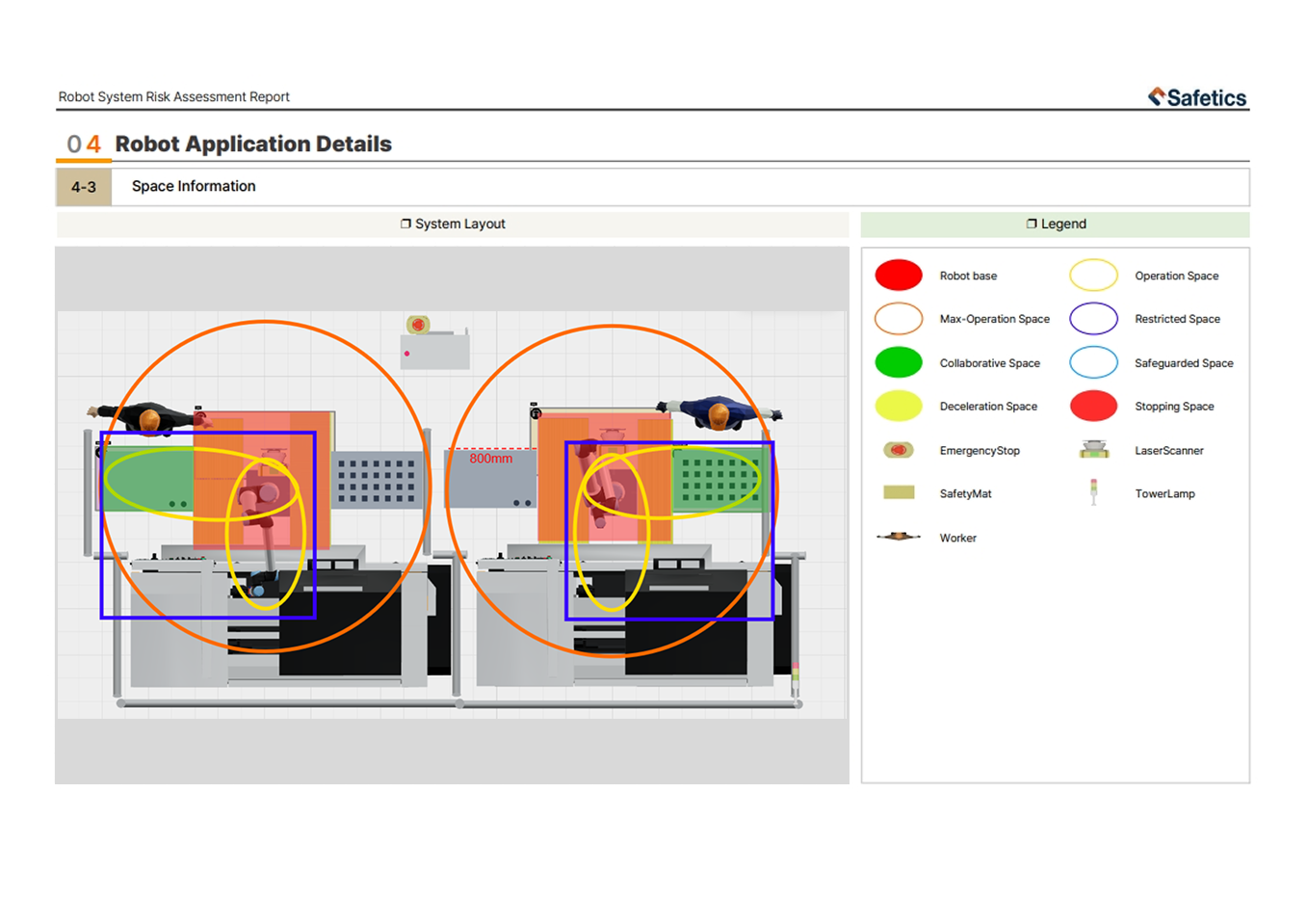
After generating a risk assessment report, you can verify the safety space information previously entered in the workspace configuration section.
3. Calculating Safety Distances for Robot Systems
Safety sensors installed in industrial robot systems must either detect the entire required safety distance from the robot’s operating space, or be installed at a distance equal to this calculated safety distance from the operating space.
The safety distance for safety sensors is calculated according to the formula provided in ISO 13855, which considers the following three factors:
🚨 This page only provides guidance on representative forms of safety distance calculation formulas specified in ISO 13855. For detailed information, please refer to the standard document itself.
① Worker’s Approach Speed (K, mm/s)
The worker’s approach speed (K) is typically assumed to be 1600 mm/s.
② Robot System Stopping Time (T, sec)
The stopping time (T) for the robot system is calculated by adding the signal output time (t1) of the safety devices and the maximum stopping time (t2) of the robot (t1 + t2). These values can be found in the datasheets provided by the safety device and robot manufacturers.
The robot’s maximum stopping time (t2) should be the maximum required time for deceleration to a stop (Stop Category 1) when the robot is carrying its maximum payload and moving at its highest speed.
③ Minimum Intrusion Distance (C, mm)
The minimum intrusion distance (C) is generally considered to be 850 mm, corresponding to the arm insertion distance.
The following examples illustrate safety distance calculations depending on the installation orientation (e.g., vertical or horizontal) of the safety sensors.
3-1. Calculating Distance According to the Orientation Between Hazard Points and Safety Sensors
① Robot systems with safety sensor detection oriented vertically to the hazard point

Use the following formula when the detection area of the safety sensor is oriented vertically relative to the hazard point—for example, when a light curtain is installed vertically or a laser scanner is ceiling-mounted and directed downward.
K × T + (8 × (d – 14)) (d = Sensing capability (of the sensor))
However, the above formula is valid only if the minimum detection capability of the sensor is 40 mm or less. For presence-sensing safeguarding devices with a detection capability of more than 40 mm and up to 70 mm, the value of C is considered to be 850.
 e.g., For a light curtain with a beam pitch of 20 mm, response time of 0.1 s, and a robot maximum stopping time of 0.4 s:
→ Safety distance (S) = 1600 × (0.1 + 0.4) + 8 × (20 – 14) = 848(mm)
② Robot systems with safety sensor detection oriented horizontally to the hazard point

Use the following formula when the detection area of the safety sensor is oriented horizontally relative to the hazard point—for example, using a laser scanner positioned at a certain height from the floor to detect human approach or installing safety mats.
K × T + (1200 – 0.4 × h) (h = height of the sensor detection plane)
e.g., For a 2D laser scanner with a response time of 0.1 s, a robot maximum stopping time of 0.4 s, and an installation height of 300 mm from the detection reference surface:
→ Safety distance (S) = 1600 × (0.1 + 0.4) + 1200 – (0.4 × 300) = 1880(mm)
🚨 This page explains how to calculate safety distances for general safety sensors. For detailed information about calculating safety distances for sensors installed diagonally, and guidelines on the installation of protective devices, refer to the ISO 13854, ISO 13855, and ISO 13857 standards.
🚨 Safety mats must have a minimum dimension of 750 mm, considering the human stride length, as specified in clause 7.1 of ISO 13855.