
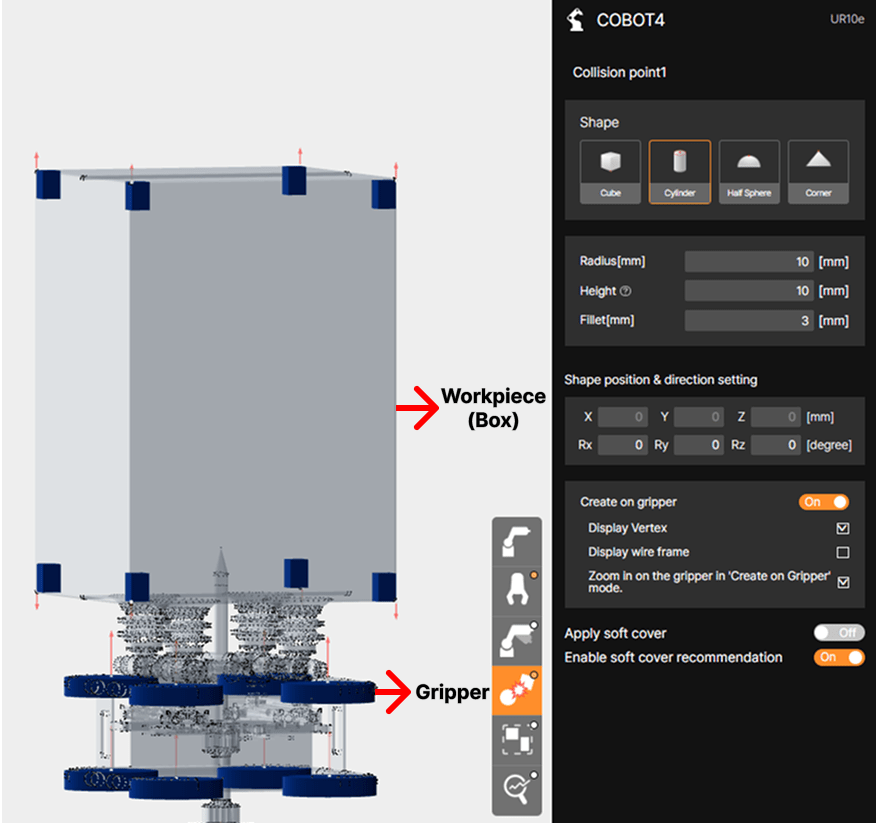
It is challenging to objectively assess risk solely by looking at the shape of the gripper or work target. Accordingly, SafetyDesigner provides a feature that allows users to upload 3D models of the gripper and working object for simulation analysis, and then designate analysis points—known as Collision Point—along the edges or cross-sections of the models.
 Collision points are configured on the gripper or working object’s 3D model. Collision points for the robot are preset on the robot model by default.
The following section examines the shapes of collision points provided by SafetyDesigner and, through examples, illustrates the scenarios in which each shape can be applied.
1. Shape of the Collision Point
After uploading the gripper file is completed, the collision point setting is required to obtain the appropriate collision analysis results.
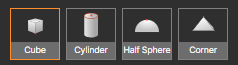
There are four possible shapes of collision points that can be set in SafetyDesigner: Cube, Cylinder, Half Sphere and Corner
① Cube
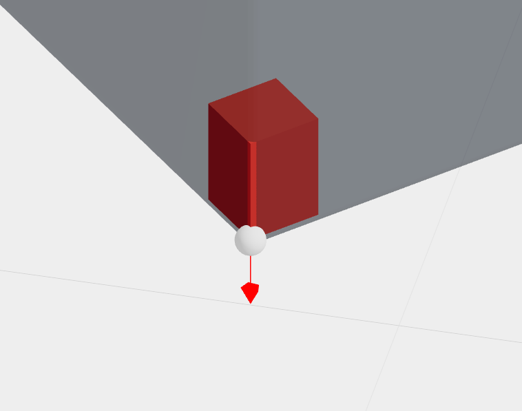
When you set the Cube shape, a cuboid appears on the 3D screen. If the gripper and the work object have rectangular edges, set them to the Cube shape as in the example in the image.
You can enter the size and fillet of the cube shape. The size does not affect the analysis.
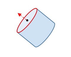
② Cylinder
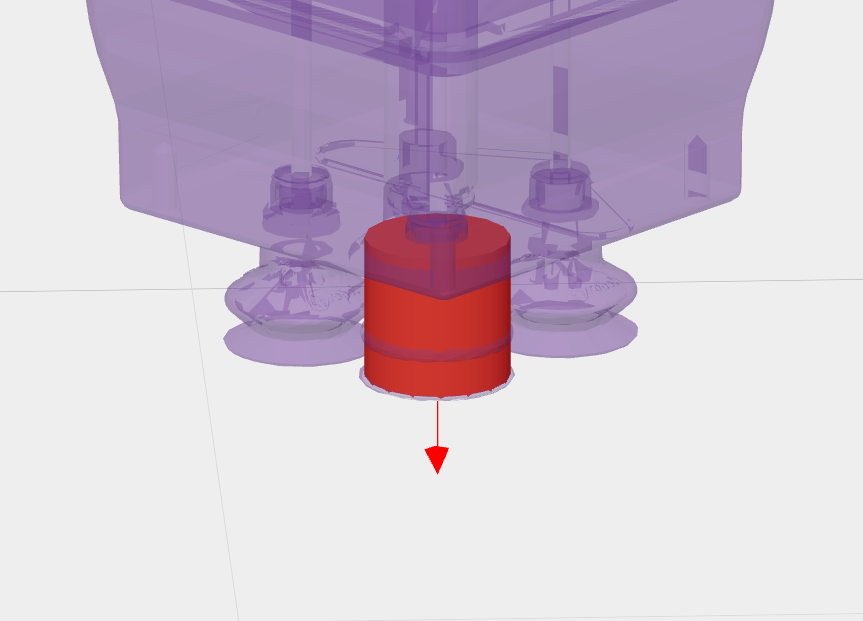
If there is a round corner section on the gripper and work object, or a cylinder shape collision point on the gripper as shown in the picture, set it to Cylinder.
Height of the cylinder can be adjusted by size input and does not affect the analysis.
Cylinder can be entered in both radius and fillet, and fillet cannot be entered larger than the size of the radius you entered.
③ Half Sphere
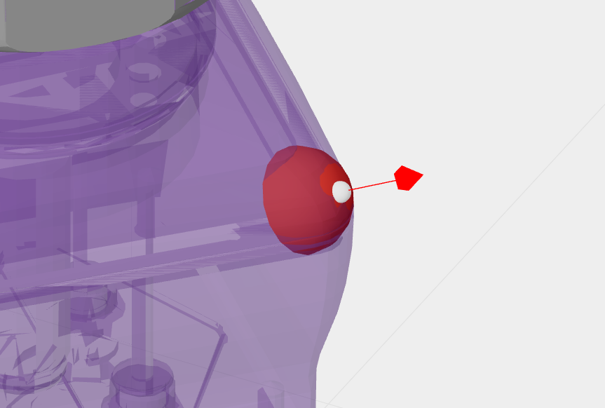
You can use the Half Sphere if the the corner of the gripper or the work object is round, as in the example of the picture.
Half Sphere does not allow fillet input, but only radius input.
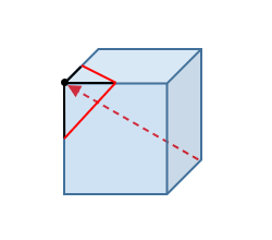
④ Corner
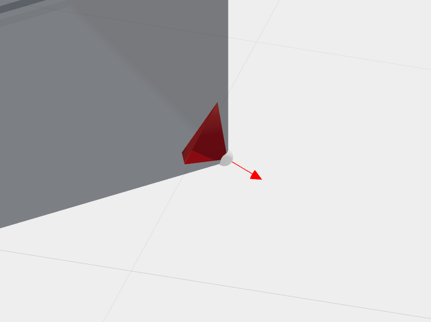
When you set the corner shape, a tetrahedron appears on the 3D screen. Use it to set the pointed edge of the gripper or work object to be worked on as the collision point.
You can enter the size and fillet of the corner shape. The size does not affect the analysis.
2. Setting the orientation of the Collision Point
In addition to the shape selection at the collision point, orientation is required to accurately position the shape in the 3D space.
You can set the direction by entering X, Y, Z coordinates and Rx, Ry and Rz values, but can also move and rotate the collision point by dragging the mouse.
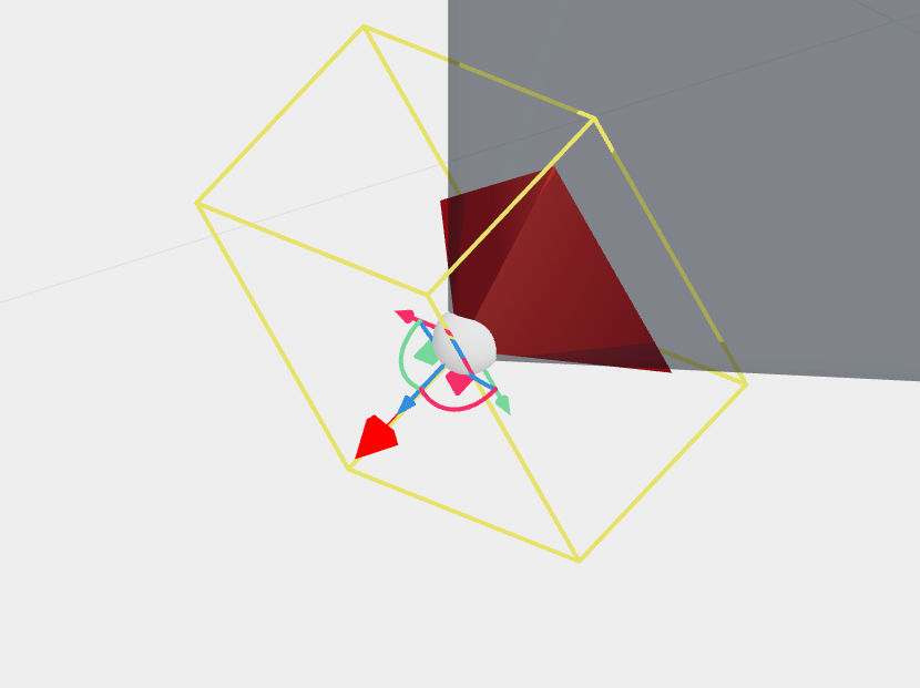
When you click on the shape, a pivot controller will appear on the 3D screen, allowing you to select parallel/rotate movement.
Click and drag the square button to move the shape in any direction; click and drag the arrow button to move in X, Y, and Z directions.
Click and drag the semicircle button between the arrows to rotate the shape in the direction of Rx, Ry and Rz.
When setting the collision point, rotate it so that the shape looks in the direction in which it actually collides.
For more information on how to create a collision point, see the Input Analysis Information(Create Collision Point) category within SafetyDesigner User Guide.