
1. 2D Layout Image and 3D Equipment
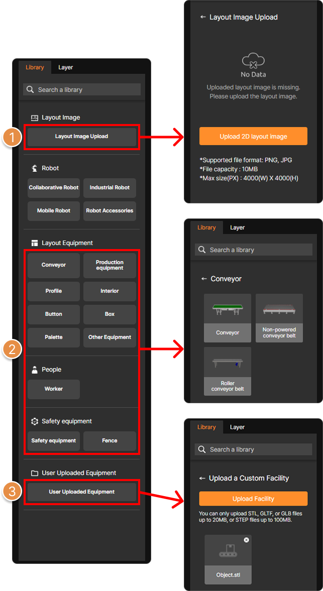
Layers Panel (Left) – Uploading 2D layout image and Placing 3D Equipment
① Layout Image Upload
You can upload and use 2D layout image. Using layout image facilitates the convenient placement of 3D equipment.
② Layout Equipment
You can use the 3D equipment library built into SafetyDesigner.
③ User Uploaded Equipment
Upload 3D CAD equipment files. You can upload STL, GLTF, GLB files under 20 MB, or STEP files under 100 MB.
Tip
You can modify the origin point of uploaded facility files to easily move or rotate it within the SafetyDesigner 3D screen. For more details, see What is 3D Mesher?.
2. Input Analysis Information (Collaborative Robots)
2-1. Gripper Settings
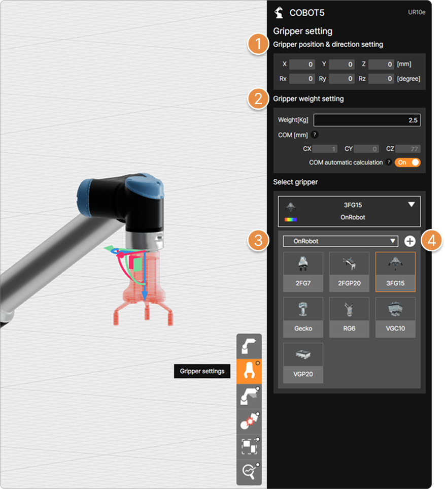
Category menu – Gripper settings
① Gripper position and direction setting
Set the position and direction of the gripper based on the robot’s last joint coordinate system position (6 axis).
② Gripper weight setting
Set the weight (Kg) of the gripper or workpiece and set the center of mass (COM).
Warning
The gripper’s weight cannot exceed the robot’s maximum payload.
③ Select gripper
You can use either built-in grippers from the library or upload your own gripper file for collision risk analysis.
④ Upload custom gripper files
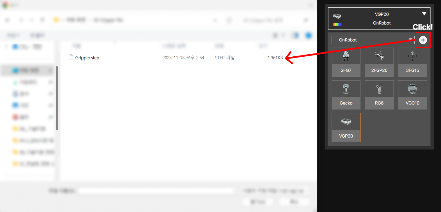
In addition to the default provided grippers, you can upload 3D gripper models to be used in the application. Gripper files can be uploaded with STL, GLTF, GLB files that are less than 20 MB or STEP files less than 100 MB.
Tip
You can modify the origin point of uploaded gripper files to easily move or rotate it within the SafetyDesigner 3D screen. For more details, see What is 3D Mesher?.
2-2. Create Collision Point
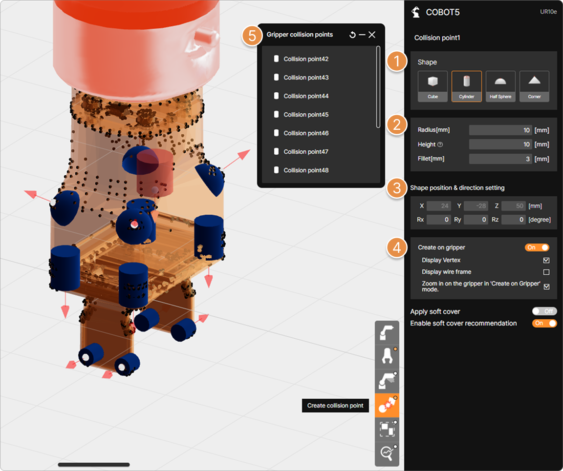
Category menu – Create collision point
① Select shape of collision point
Select a shape to represent a collision point between the worker and the gripper or workpiece. After selecting the desired shape, click the desired location on the 3D screen with the mouse to create a collision point.
Tip
For more information about the collision point, see What is Collision Point?.
② Radius, Size(Height) and Fillet setting
You can set the radius, size (height), and fillet size of the created feature. The size input is a convenience feature for making certain features more visible on the 3D screen, and does not affect the analysis.
Tip
The properties you can enter for each shape are as follows.
- Cube – Size, Fillet
- Cylinder – Radius, Height, Fillet
- Half Sphere – Radius
- Corner – Size, Fillet
③ Shape position and direction setting
Enter the location and direction of the collision point that you want to create.
Warning
The location of the collision point can be moved from -1000 mm to 1000 mm based on the origin of the gripper and the direction can be entered from -180° to 180°.
④ Create on gripper
Restricts collision point creation to only within the bounds of the gripper 3D model.
Using the Display Vertex or Display Wireframe feature makes points and a wireframe appear on the edges of the gripper 3D model, allowing for easier creation of collision points.
⑤ Collision points information
You can view or edit the information of the collision points that you have created.
2-3. Motion Settings
This section explains two methods for configuring robot motion.
2-3-1. Motion Settings 1 (Motion Upload)
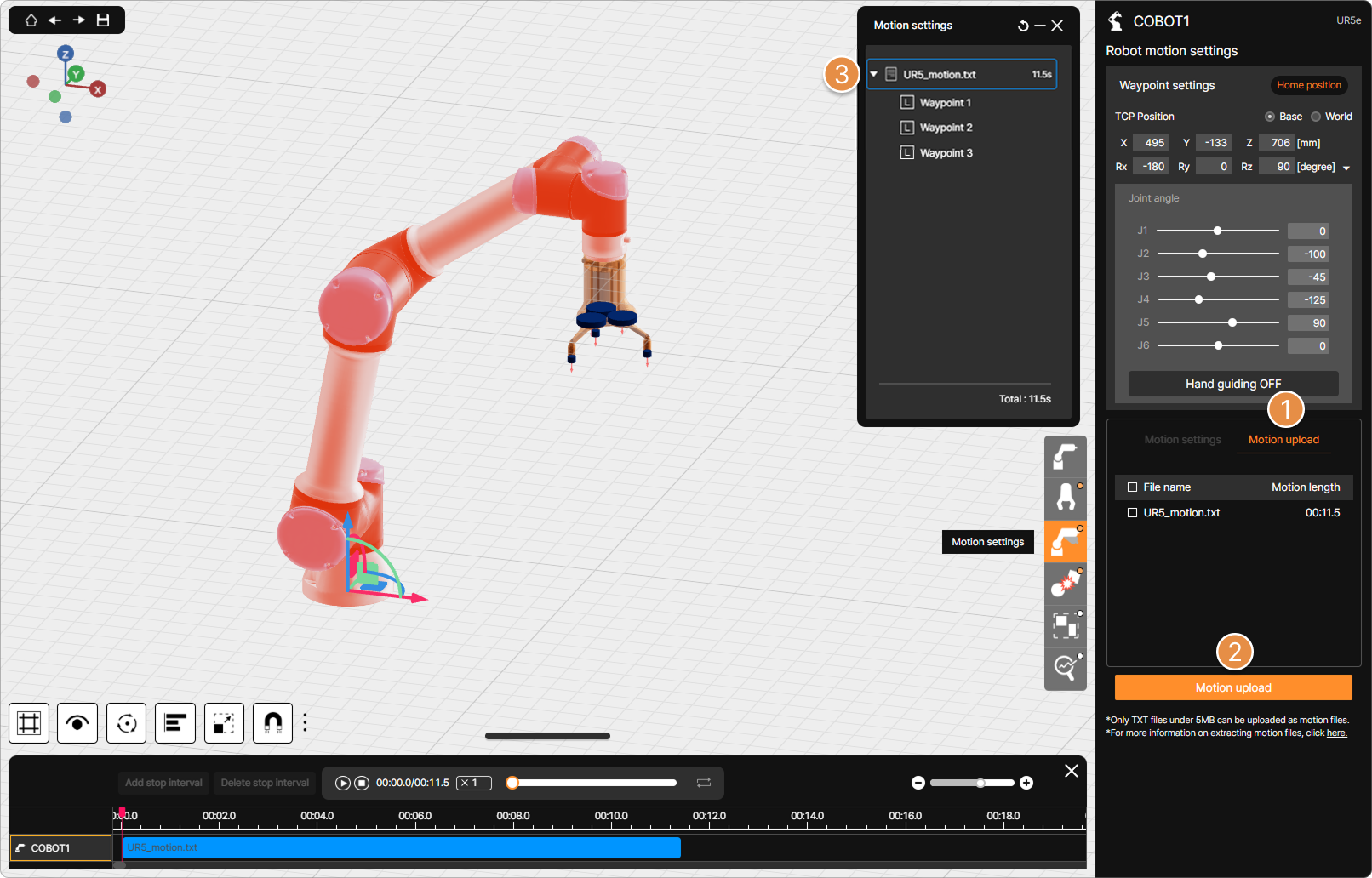
Motion settings – Upload motion
① Motion upload tab
You can upload motion files extracted from an actual robot.
Tip
For more information about extracting motion files, see Motion Extractor Guide.
② Motion upload
Upload the motion file in the *.txt format extracted using the motion extractor program.
③ Waypoint List
You can view the waypoint information of the motion file that you have uploaded.
Warning
The waypoints of the uploaded motion are virtual waypoints calculated by SafetyDesigner’s algorithm, so they may differ from the actual configured values.
2-3-2. Motion Settings 2 (Create Motion)
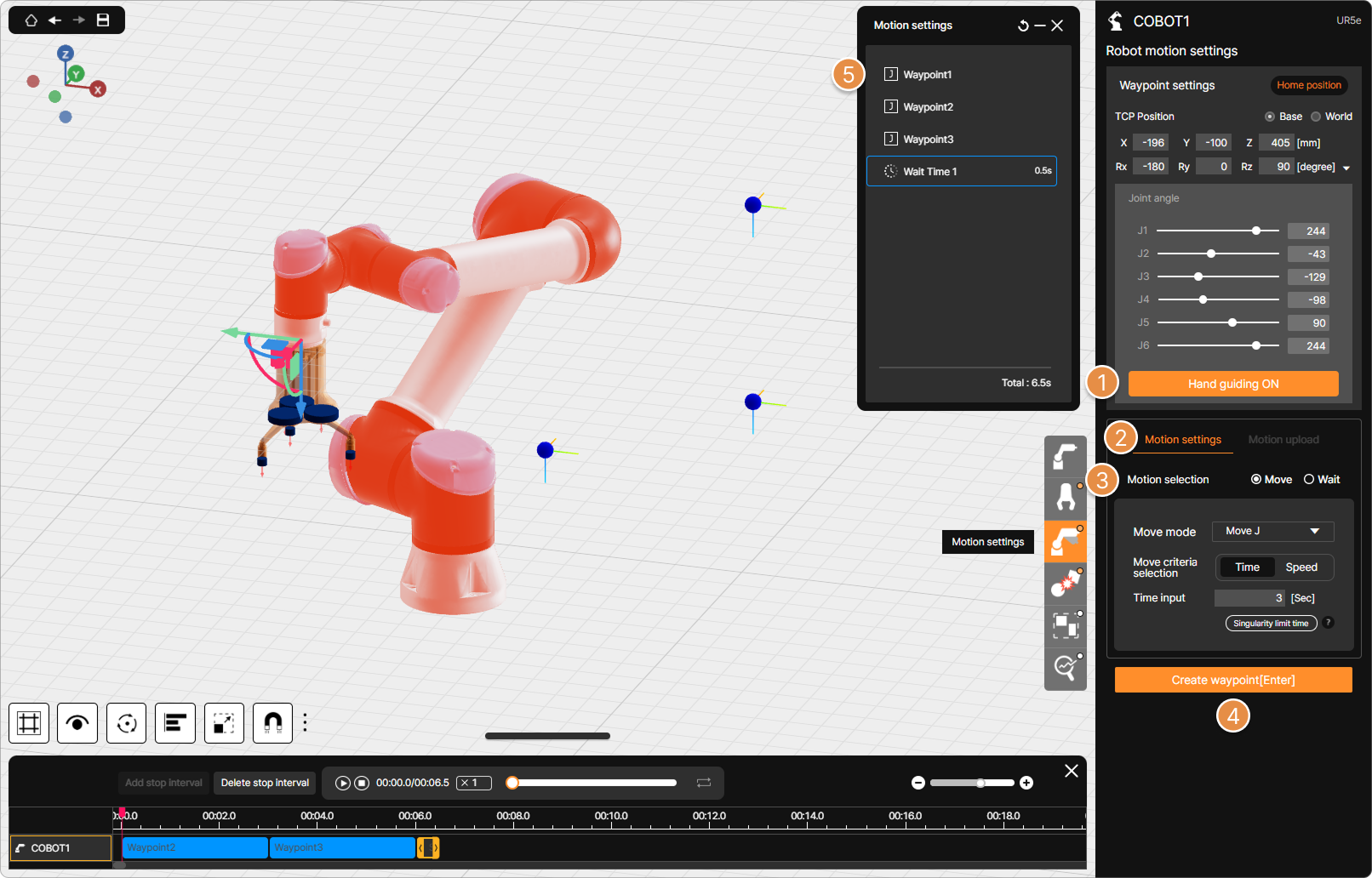
Motion settings – Create motion
① Hand guiding ON/OFF
When Hand Guiding is ON, you can create waypoints by teaching the robot on the 3D screen.
Tip
Some robots may not be able to use the motion creation (Hand guiding) feature, depending on the development status.
② Motion settings tab
Enter the Motion Creation (Waypoint Settings) menu.
Tip
For more information about the motion creation feature, see What is Motion Create?.
③ Motion selection
Select either a move motion or a stop motion (Wait time), then configure the waypoint.
④ Waypoint Creation
Save the robot’s current position as a waypoint to create the motion. Created waypoints are displayed as blue dots on the 3D screen.
⑤ Waypoint List
A list of created waypoints and stop motions (Wait time) is displayed. Select a specific Waypoint from the list to modify its settings.
3. Input Analysis Information (Mobile Robots)
Tip
Integration with the mobile robot is currently limited to collaborative robot models.
3-1. Path Point Settings
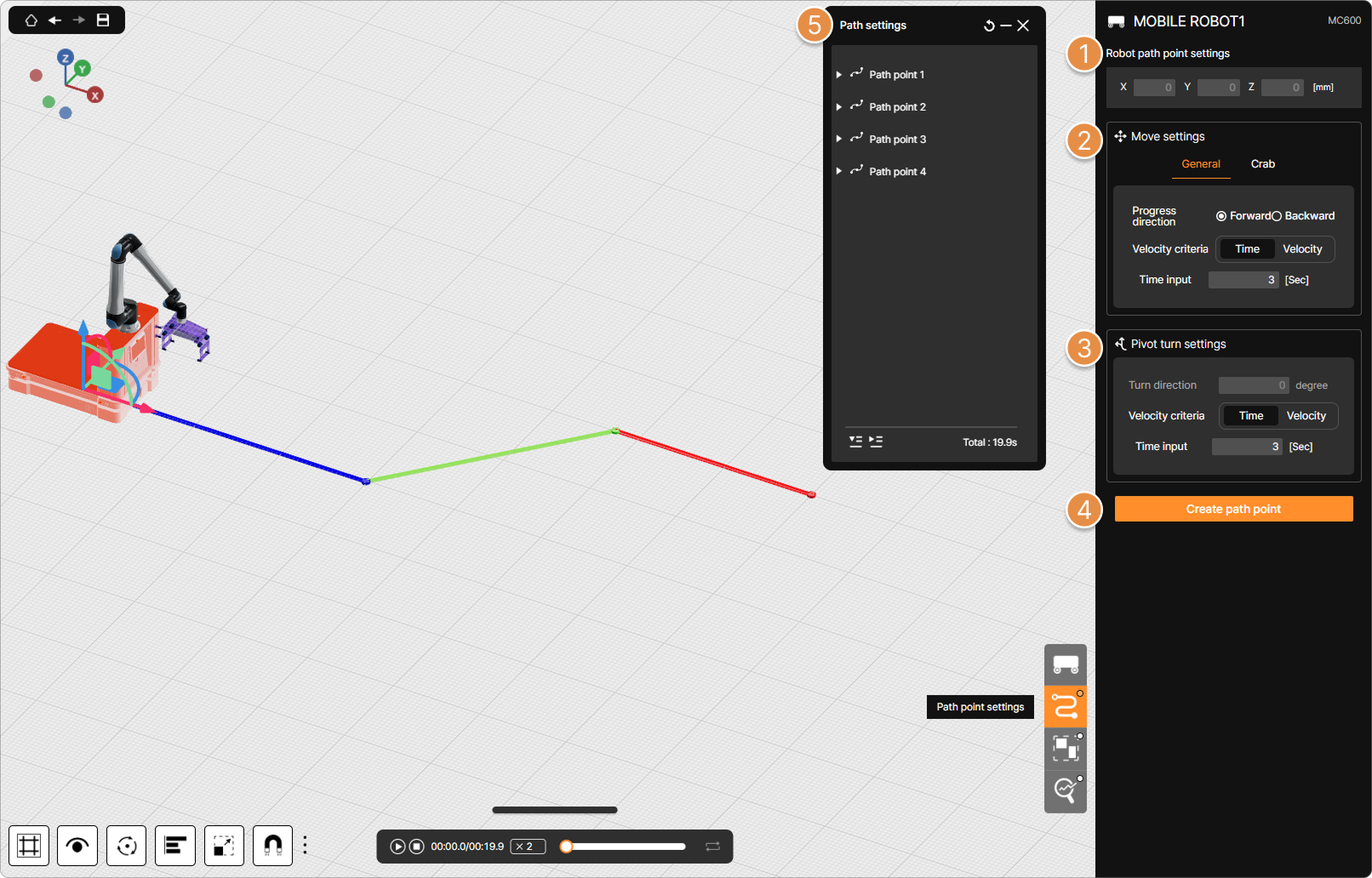
Category menu – Path point settings
① Robot path point settings
When path creation is initiated by clicking the Create path point button, the X and Y coordinates of the mouse cursor’s position are displayed, and a Path Point is created based on these coordinates. If an existing Path Point is clicked, its position can be modified by directly entering X and Y coordinate values in the relevant menu.
② Move settings
When creating a Path Point, the mobile robot’s movement type (General/Crab), Progress direction (Forward/Backward), and Velocity criteria (Time/Velocity) can be configured.
③ Pivot turn settings
If the mobile robot needs to rotate before moving to the next point (e.g., when changing state from forward to backward), the turn direction, rotation speed or rotation time for that rotation can be configured.
④ Create path point
A robot’s travel path is constructed by creating Path Points based on the values configured above. With a creation mode enabled (after clicking the Create path point button), a sequence of Path Points can be made by clicking desired locations on the 3D screen.
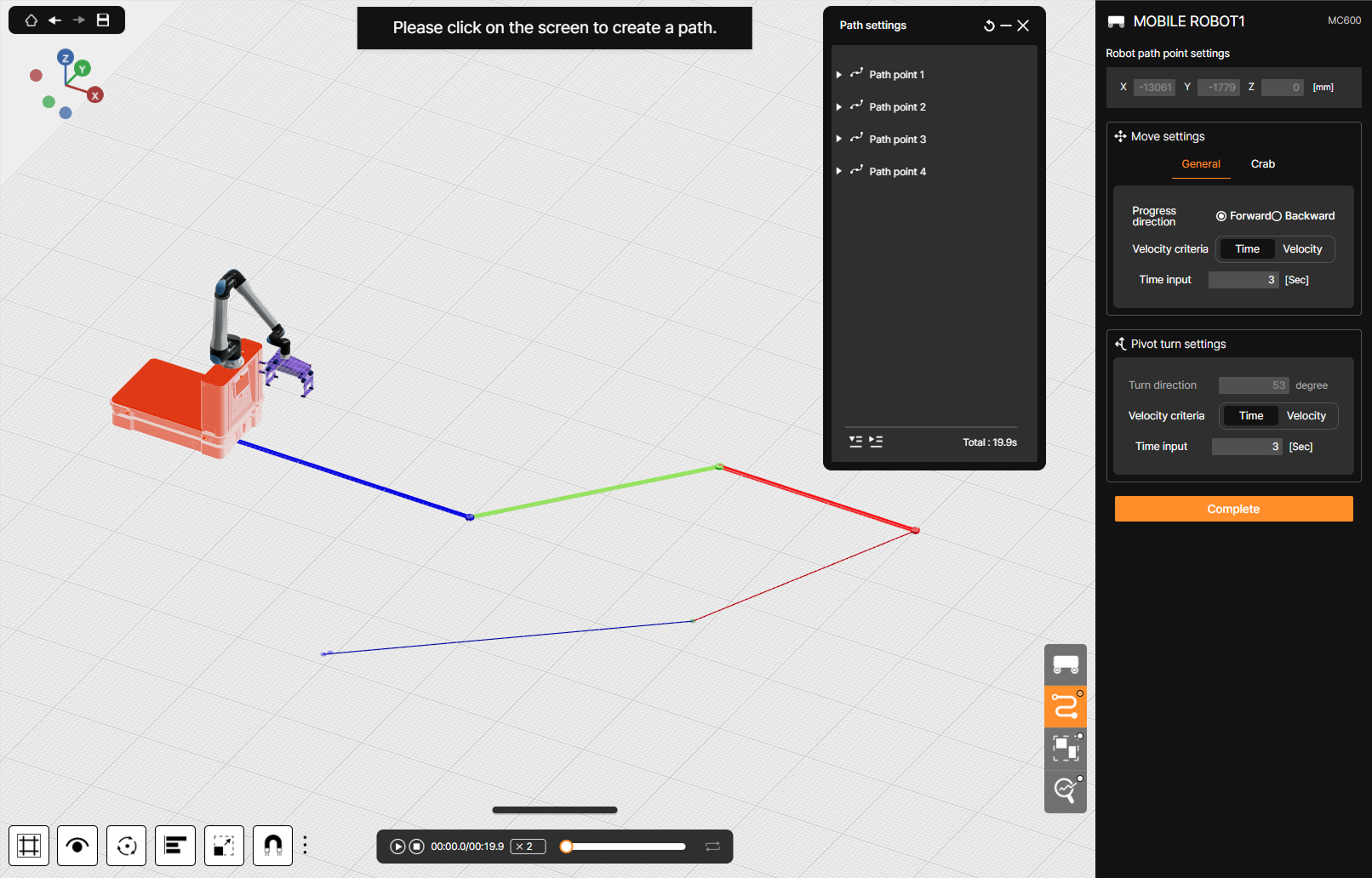
Forward path segments are displayed in blue, backward path segments in red, and Crab move path segments in green.
⑤ Path point List
A list of Path Points for the selected mobile robot is displayed.
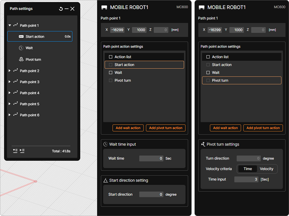
Clicking the expand/collapse button (▼) to the left of each Path Point displays a menu on the right side of the screen where detailed settings for movement to that point and related actions can be modified.
4. Collaborative Workspace Settings
Collaborative workspace refers to a workspace shared by robots and humans for collaborative applications.
When configuring the collaborative workspace, except in cases where protective measures (e.g. safety fences, electro-sensitive protective equipments) have been installed to ensure that the possibility of accessing the robot is zero, the collaborative workspace must be set up without any gaps across all operating spaces of the robot.
Furthermore, there must not be any collaborative workspace configured in empty areas outside the robot’s operating spaces that results in a CRI value of 0 in the analysis.
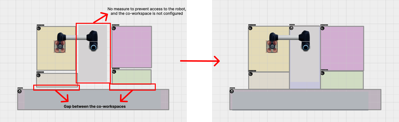
Examples of incorrect co-workspace configuration
The following section explains how to use the collaborative workspace configuration menu.
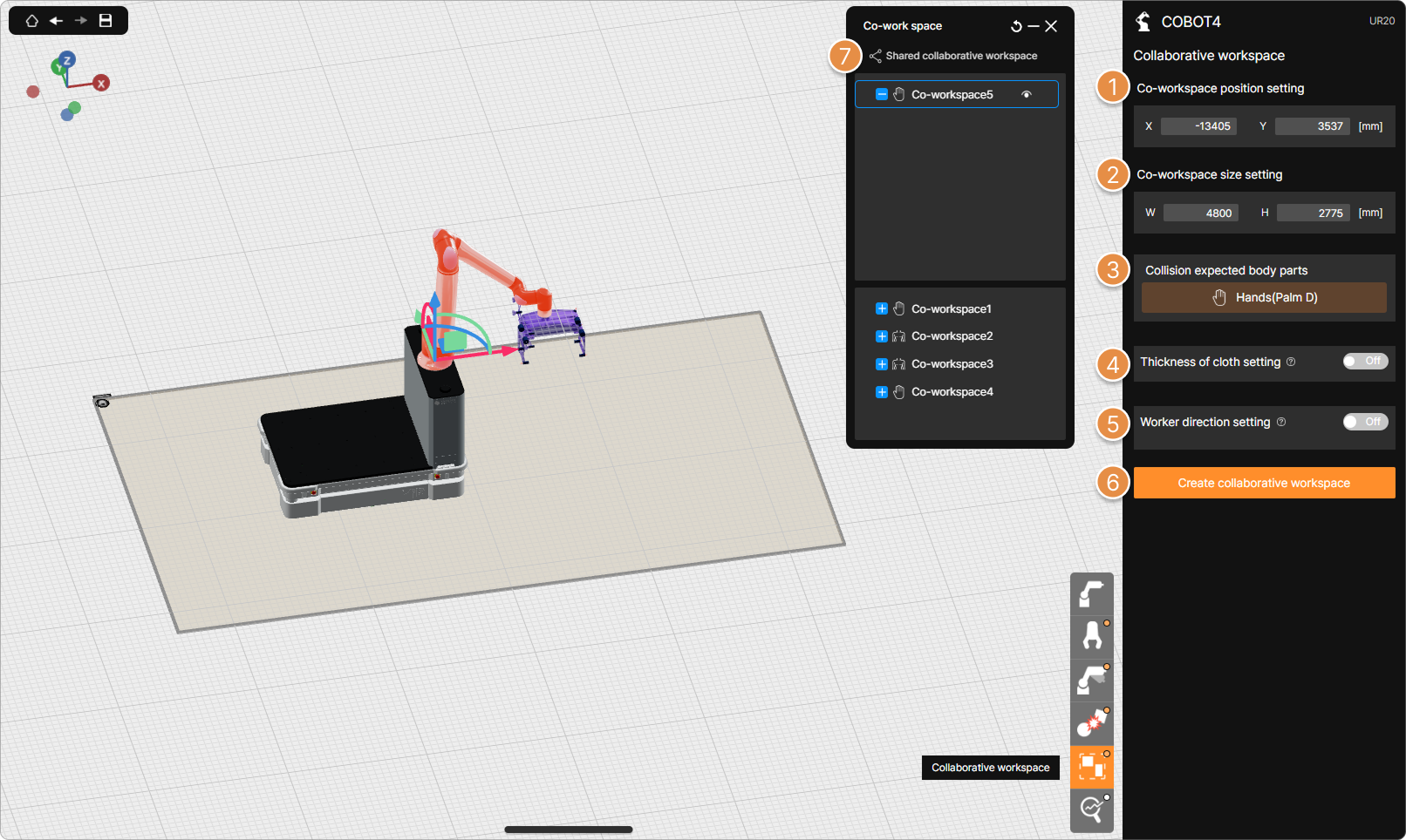
Category menu – Collaborative workspace
① Co-workspace position setting
Enter the position (mm) of the collaborative workspace.
Tip
The configurable position range for the collaborative workspace is from -20000 mm to 20000 mm.
② Co-workspace size setting
Enter the size (mm) of the collaborative workspace.
Tip
The configurable size range for the collaborative workspace is from 150 mm to 10000 mm.
③ Collision expected body parts
Within the collaborative workspace, set the worker’s body part that is expected to collide with the robot.
When a collaborative workspace is created, the default body part is fixed as Hand (Palm); the body part can be changed when modifying the collaborative workspace.
Warning
Standards (ISO/TS 15066, KOROS 1162-1) do not permit dynamic collisions involving the head.
Tip
The types of collision expected body parts are as follows.
- Hand (Palm)
- Chest (Sternum)
- Upper Arm (Deltoid muscle)
- Lower Arm (Forearm muscle)
- Thigh (Thigh muscle)
④ Thickness of cloth setting
Assuming the worker in the collaborative workspace is wearing clothing of the specified thickness.
Tip
Thickness can be set from 1 mm to 2 mm.
⑤ Worker direction setting
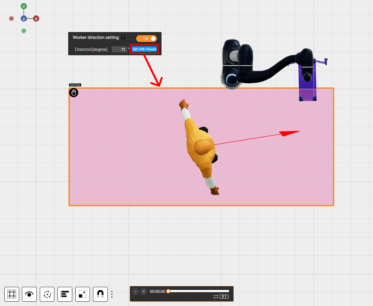
To calculate only actual potential collisions, set the direction the worker faces when operating within the collaborative workspace. Clicking the Set with mouse button with the mouse displays a worker model in the collaborative workspace; rotate the model to the desired orientation to specify the worker’s direction.
In collaborative workspaces where this feature is applied, the ‘Chest’ and ‘Upper Arm’ body parts are merged and analyzed as a single region by an internal algorithm.
⑥ Create collaborative workspace
Configure the collaborative workspace on the 3D screen. The collaborative workspace is defined as a rectangular shape by dragging with the mouse on the floor area of the 3D screen.
⑦ Co-workspace List
Clicking the + or – buttons located to the left of the collaborative workspace name allows that workspace to be included in or excluded from the analysis for the currently selected robot.
Tip
Multiple robots can share and use a single collaborative workspace.
5. Analysis Option
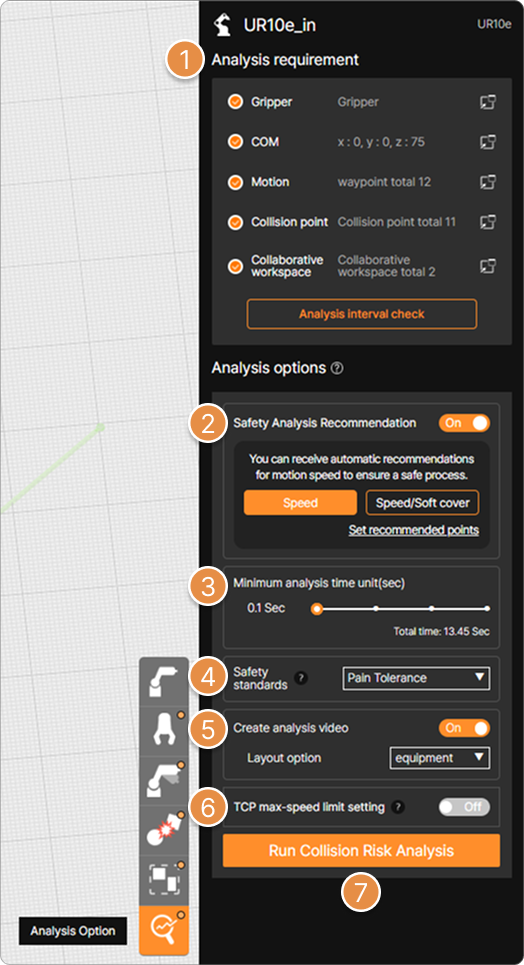
Category menu – Analysis option
① Analysis requirement
Analysis information entered for the selected robot is listed. An orange check button is displayed to the left of items for which analysis information input is complete.
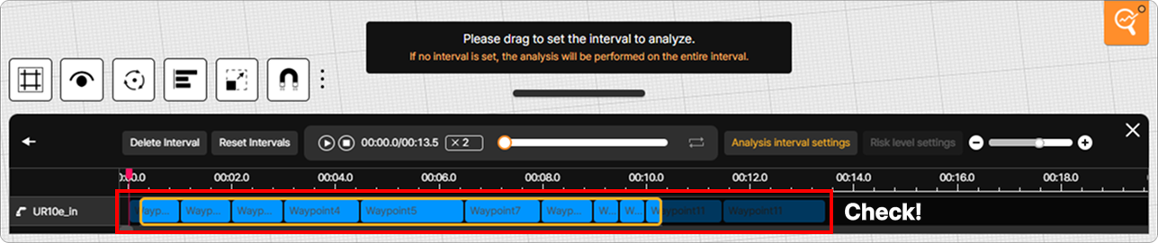
Clicking the Analysis interval check button displays a selection area at the bottom of the screen where the segment of the robot motion to be analyzed can be specified by dragging with the mouse.
② Safety Analysis Recommendation
Based on analysis results, recommendations are provided regarding acceleration/deceleration adjustments for each robot motion segment and the necessity of applying a Soft cover. The Safety Analysis Recommendation feature is not applicable to mobile robots or to collaborative robots that are combined with mobile robots.
Tip
For more information about the Safety Analysis Recommendation, see What is Safety Analysis Recommendation?.
③ Minimum analysis time unit (sec)
You can choose the unit of analysis time. The smaller the value, the more accurate the results and the longer the analysis time.
Warning
When generating the Collision Risk Analysis Report, the minimum analysis time unit must be set to 0.1 sec.
④ Safety standards
Choose a reference standard for collision risk analysis.
Tip
Each standard is as follows.
- Pain Onset (ISO TS 15066): Run analysis based on the figure of pain starting point that people can feel. (International Standard)
- Pain Tolerance (KOROS 1162-1): Run the analysis based on the highest level of pain a person can tolerate. (Korean Standard)
⑤ Create analysis video & Layout option
Choose whether to generate a video during the analysis. Selecting video generation will result in additional time required for the analysis.
Warning
Collision Risk Analysis Report cannot be issued unless the analysis video is generated.
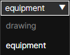
Additionally, choose whether to display elements from the drawing or the equipment in the analysis video.
⑥ TCP max-speed limit setting
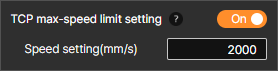
Limit the maximum speed of the robot’s motion. During motion, any intervals that exceed the value entered in the speed setting will be adjusted to the set speed and analyzed.
⑦ Run Collision Risk Analysis
Click to run the analysis. The time it takes to analyze depends on the length of the motion.