
ISO 10218-2:2025 Revision Guide
Key changes and practical response guidance for system integrators and robot users
1. Why the standard was revised
When the 2011 industrial robot safety standard first appeared, robots were still viewed mainly as machines performing repetitive tasks inside isolated spaces. AI-enabled automation and wired or wireless networked systems were far less mature, and the related risks were not yet a major focus of safety discussions.
Over the following fourteen years, robotics broke down both physical and technical boundaries, and the broader shift associated with Industry 4.0 forced a major change in the traditional safety paradigm.
Robots now work closer to people; automation systems are connected in real time through technologies such as IoT and digital twins; and new robot forms and more dynamic applications are also beginning to appear in industry.
The earlier edition was not sufficient to frame the risks created by intelligent and networked robot applications on its own. The revised ISO 10218-2 represents a major expansion of scope and structure, reflecting the scale of change in real industrial environments—a redefinition of the safety baseline and clearer guidance where boundaries used to be blurred.
Six main drivers of the revision
2. Key changes
Four headline changes are summarised below. Each compares the previous edition with ISO 10218-2:2025, cites clause numbers, and highlights implications for system integrators and end-users.
Take-away: The integrator shall assess risks for the robot application and robot cell, including workpiece size, geometry and hazards, program path and speed, and all related machinery—not the robot in isolation.
| Collaborative safety function | Previous edition (5.11.5) | 2025 edition (5.14) |
|---|---|---|
| Safety-rated monitored stop | Listed as one type of collaborative operation | 5.5.8 — Redefined as the monitored standstill safety function |
| Hand-guided control (HGC) | Only four high-level requirements | 5.14.4 — Detailed design requirements for guiding devices; monitored standstill when HGC is not active |
| Speed and separation monitoring (SSM) | Note referring to ISO/TS 15066 “in preparation” | 5.14.5 + Annex L (normative) - Separation distance: Sp = Sh + Sr + Ss + C + Zd + Zr - Sh (human approach) · Sr (reaction-time contribution) · Ss (distance during stopping) · C (intrusion distance) · Zd (detection uncertainty) · Zr (robot position uncertainty) - Variable definitions and calculation methods in Annexes L.1–L.3 |
| Power and force limiting (PFL) | Note referring to ISO/TS 15066 “in preparation” | - Distinguish ① quasi-static contact (clamping/crushing) and ② transient contact (impact and rebound) - Body-region limit values from ISO/TS 15066 in Annex M - Forces and pressures may be verified with a pressure and/or force measuring device (PFMD), or estimated using the calculation method described in Annex M, M.3.4 where applicable |
| Topic | Previous edition | 2025 edition |
|---|---|---|
| Achieving PL d Performance level (PL): reliability of a safety function (a–e). PL d was the default target in the robot field. |
Category 3 architecture required (fixed) | - Previous edition: only dual-channel (Category 3) was accepted - 2025: if average probability of dangerous failure per hour (PFHD) is less than 4.43×10⁻⁷/h (ISO 10218-2:2025, 5.5.3), other architectures may be used—more design flexibility |
| How performance is determined PLr = required performance level; SIL = safety integrity level |
PL d applied uniformly to all safety functions | - No longer one level for every function - ① Select from tables in the standard’s annexes, or - ② Determine PLr/SIL per function from the risk assessment - Lower risk → lower PLr; critical functions → higher PLr |
| PL d with Category 2 Category: structural category of the safety-related control system (1–4). DCavg = average diagnostic coverage; MTTFD = mean time to dangerous failure |
Not specified | - Single-channel (Category 2) may achieve PL d if DCavg > 90 % and MTTFD > 62 years - Broader use of electronic safety systems (e.g. safety PLCs) Source: ISO 10218-2:2025, 5.5.3, Note 2 — “DCavg > 90 % & MTTFD > 62 years” |
| Safety-function parameters Numerical settings such as speed limits, stopping distances, detection zones |
No parameter protection requirements | - New requirements to prevent unauthorised change of safety-related settings (e.g. speed limits, detection distances) - Only authorised persons may change settings; restart after change; automatic logging of changes - No changes while the robot is in automatic operation |
| Security of communications | Not addressed | - If data communication implements safety functions, apply IEC 61508-2:2010, 7.4.11 (5.5.9) - Networks classified in three transmission categories; apply countermeasures appropriate to repetition, loss, insertion, re-ordering, corruption, delay, masquerading, etc. - Safety networks and fieldbuses must be covered in verification checklists |
⚠️ 5.2.16 Cybersecurity — new in the 2025 edition
Requirement 1: A cybersecurity threat assessment shall be carried out.
Requirement 2: If threats can give rise to safety-related risks:
- Measures shall prevent unauthorised access to control-system hardware, software, configuration data, and application programs.
- Examples include: blocking access to communication ports (TCP/UDP); ability to change port numbers; protection of safety configuration by authentication; ability to change default settings (user names, passwords, IP addresses, safety certificates).
Related reference standards (cybersecurity):
- ISO/TR 22100-4:2018 — Relationship of machinery safety to ISO 12100; guidance on IT security (cybersecurity)
- IEC TS 63074:2023 — Machinery safety — Security aspects related to functional safety
- IEC 62443-3-3:2013 — Industrial communication networks — System security
3. Stop functions and speed-related safety functions
Concepts that were unclear in the previous edition are now defined as independent safety functions or are newly added in ISO 10218-2:2025.
In particular, there were no clear requirements for stops during normal workflow—for example at end of cycle, tool or part change, or material replenishment—so emergency stop was often misused as a routine stopping means.
① Normal stop (5.6.4)
| Emergency stop (5.6.2) | Protective stop (5.6.3) | Normal stop (5.6.4) New | |
|---|---|---|---|
| Purpose | Respond to immediate danger | Automatic stop on safety-device signal | Planned stop within normal workflow |
| Initiation | Manual actuation by the operator | Internal safety function or external protective device | Normal-stop control device at the control station |
| Performance | PL c or higher (Annex C, Table C.1) | PL d or higher (Annex C, Table C.1) | PL b or higher (Annex C, Table C.1) |
| Stop category | 0 or 1 | 0, 1 or 2 | 0 or 1 |
| Dual use | Shall not be used as normal stop | May serve as normal stop if stop category 0 or 1 is applied | — |
⚠️ 5.6.4 normal stop — essentials
With the introduction of normal stop, emergency-stop devices shall not be used as normal-stop devices.
Because it is routine stopping, PL b is the minimum, but after stopping, energy to the actuators shall be removed as required for safety.
If protective stop uses stop category 0 or 1, it may be used as normal stop.
② Monitored standstill (5.5.8) — change of concept
In the previous edition, “safety-rated monitored stop” appeared only as one collaborative operation type. In the 2025 edition it becomes an independent safety function and is typically needed where stop category 2 is used to maintain position with drive power active and unintended motion has to be prevented, not only in collaborative applications.
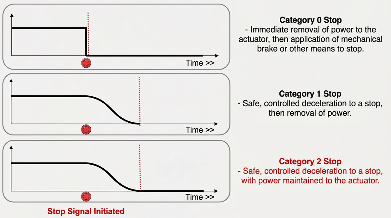
What is stop category 2?
IEC 60204-1 defines stop categories 0, 1 and 2. Category 2 stops motion without removing motor power, enabling fast restart and holding position—suited to collaborative applications where people and robots share space.
Because power remains applied while stationary, lack of motion shall be monitored continuously—hence the monitored standstill safety function.
The previous “safety-rated monitored stop” is renamed monitored standstill (5.5.8) and elevated from a note inside collaborative operation to a standalone safety function. It is typically needed where stop category 2 is used to hold position with drive power maintained and unintended motion has to be prevented.
Examples of monitored standstill
- End of HGC — When the operator releases the guiding device, the system transitions to monitored standstill. With power still applied at that pose, HGC can resume when the device is grasped again. If motion occurs after release (e.g. control fault), monitored standstill shall initiate stop category 0 or 1
- SSM with operator approach — If separation distance is violated, speed is reduced to zero and the robot waits with power on; automatic resumption is only possible once the required separation distance is maintained and no people remain within the SSM safeguarded space. If during waiting a fault or vibration causes motion outside the defined limits, monitored standstill shall initiate stop category 0 or 1
③ Reduced speed (3.1.8.6) — new defined term
What is reduced speed?
In manual mode, when the operator shares space with the robot, TCP speed shall not exceed 250 mm/s.
250 mm/s has long been used as a de facto limit in industrial robot standards; ISO 10218-1 and ISO 10218-2:2025 define reduced speed as a formal term applied across the standards.
If higher speed is needed (e.g. program verification), it is permitted only under the additional safeguards of high-speed manual mode (5.7.2.3.3).
④ Additional axis (5.2.9) — new
Clause 5.2.9 introduces dedicated requirements for additional axes connected to the robot (e.g. lifts, tracks, positioners).
📌 Three essentials for additional axes
- Apply related clauses: 5.2.1 (materials/strength), 5.2.2 (mechanical design), 5.2.8 (position holding), 5.5 (safety functions), 5.6 (stopping), 5.7 (control) apply to additional axes as well
- Reduced speed: If additional-axis motion can affect TCP speed in reduced-speed manual mode, apply 5.5.6.1 to that axis
- Synchronised axes: Provide safeguarding or safety functions where speed differences between synchronised additional axes create risk
⚠️ Special rules for additional-axis alignment or uncoupling
- High-speed manual mode (5.7.2.3.3): May be used only for alignment/uncoupling moves of the additional axis, with monitored-speed parameters set
- When the additional axis moves faster than reduced speed: Automatic operation of the other axes (robot arm) is not permitted—prevent simultaneous high-speed additional-axis motion and automatic robot motion
⚠️ Additional axis on the robot base — key points
① Automatic mode: If safety is assured by safeguarding (fencing, sensors) or PFL, there are no separate requirements for simultaneous motion or speed limits between additional axis and robot.
② Manual mode: If the robot and additional axis move together so that the additional axis contributes to TCP speed, the combined TCP speed (robot + additional axis) shall not exceed 250 mm/s.
4. Detailed comparison by topic
The tables below compare the previous edition with ISO 10218-2:2025. Badge colours indicate the type of change.
Structure — Clauses 1 to 7
| Clause | Type | Previous edition | 2025 edition |
|---|---|---|---|
| 1 | Revised | Scope: integration of industrial robot systems and cells Exclusions not listed | Scope reframed as industrial robot applications and robot cells Exclusions: eleven application fields stated (e.g. underwater, medical, military) Hazards not covered: thirteen categories listed |
| 2 | Expanded | Approx. 20 normative references | Approx. 40 normative references Updated editions, e.g. ISO 14119:2024, ISO 13849-1:2023 |
| 3 | Expanded | Terms and definitions: 15 Abbreviations table: none | Title expanded to Terms, definitions and abbreviated terms 3.1 78 terms in 12 groups 3.2 Abbreviated terms and symbols — new |
| 4 | Revised | Title: hazard identification and risk estimation Subclauses 4.2 (layout) through 4.5 (risk reduction) | Title: Risk assessment 4.1 General — explicit use of ISO 12100 4.2 Robot application and robot cell characteristics (22 task types) 4.3 Characteristics of collaborative applications (new) |
| 5 | Expanded | Safety requirements and protective measures — 12 subclauses (5.1–5.12) | Safety requirements and risk-reduction measures — 16 subclauses (5.1–5.16) 5.2 Design, 5.5 Safety functions, 5.6 Stopping, 5.7 Control, 5.8 Safeguarding, 5.9 End-effectors, 5.14 Collaborative applications — major restructuring |
| 6 | Revised | Verification and validation of safety requirements and protective measures Means of verification: Annex G (normative) | Title: Verification and validation 6.3.3 New: verification of PFL biomechanical limit values Means-of-verification table moved to Annex H (informative) |
| 7 | Expanded | Structure: 7.1–7.3 7.2 Instructions — 10 items; 7.3 Marking | Structure: 7.1–7.5 7.2 Acoustic/visual signals; 7.3 Displays; 7.4 Warnings and caution statements (new) 7.5 Instructions — 23 items (7.5.1–7.5.23), including cybersecurity (7.5.23) and functional-safety information (7.5.16) |
Key terminology changes (Clause 3)
| Term | Type | 2025 edition — term / clause | Change |
|---|---|---|---|
| Collaborative robot | Removed | Term removed — replaced by collaborative application (3.1.1.6) and collaborative task (3.1.1.7) | Major shift: whether an application is collaborative is determined by the application, not the robot alone |
| Robot application | New | Broader than the previous “robot system (robot + end-effector + sensors)” Defined as a complete machine including workpiece geometry and hazards, robot program, and associated machinery | Core unit for risk assessment and safety design in the 2025 edition |
| Integrator | Strengthened | The integrator may be considered the manufacturer of the robot application or robot cell—not only an installer (3.1.7.2) Basis for stronger legal and safety accountability | Clarifies when the integrator holds manufacturer status |
| Separation distance | New | Minimum safe distance to be maintained between the operator and moving parts of the robot application; SSM calculates it in real time and reduces speed or stops the robot if violated | Central to SSM: maintain minimum distance using the formula in Annex L |
| Quasi-static contact | New | Contact where a body segment can be clamped between moving parts of the robot application and other fixed or moving parts | PFL — stricter limits (clamping). Fmax = max permissible force per body region (N); Pmax = max permissible pressure (N/cm²) |
| Transient contact | New | Contact without clamping, where the body segment can retract or rebound from moving parts of the robot application | PFL — higher permissible values. Transient limits use twice the quasi-static values (per standard) |
| Monitored standstill | New | With stop category 2 and power not removed, the safety function continuously verifies absence of motion; on fault, transition to full stop (category 0 or 1) | Commonly used with stop category 2 where unintended motion needs to be prevented — 5.6.3 c), 5.5.8 |
| Spaces and zones | Expanded | 3.1.9 Spaces, zones and distances — expanded to ten concepts; hazard zone, operating zone, detection zone, separation distance added | Four space concepts refined into ten New definitions for detection zone (SPE) and separation distance for SSM |
| Collaborative workspace | Removed | Term removed — concepts absorbed into safeguarded space (3.1.9.6) and collaborative task (3.1.1.7) | Unified wording: collaborative tasks within the safeguarded space Clearer structure |
| Industrial robot line | Removed | Term removed | Line of connected robot systems is subsumed under robot cell; separate definition no longer needed |
Safety requirements — Clause 5 (detail)
| Subclause | Type | Previous edition | 2025 edition |
|---|---|---|---|
| 5.2 Design | Expanded | SRP/CS performance: fixed PL d / SIL 2 | Restructured as 5.2.1–5.2.16 Materials/strength, mechanical design, lifting/travel, hazardous substances, stability, temperature/fire, special equipment Loss of power, malfunction, hazardous energy, electrical/pneumatic/hydraulic; TCP / payload settings New: cybersecurity (5.2.16) |
| 5.2.9 Additional axis | New | No dedicated additional-axis requirements — covered only by general design | New subclause for additional axes (base lift, track, positioner, etc.) Same obligations under 5.2.1, 5.2.2, 5.2.8, 5.5, 5.6, 5.7 If motion affects TCP speed in reduced-speed manual mode, apply 5.5.6.1 to the additional axis Safeguard or safety functions for speed differences between synchronised additional axes If additional axis moves faster than reduced speed → no automatic operation of other axes (robot arm) |
| 5.2.16 Cybersecurity | New | No subclause | New cybersecurity requirements Cybersecurity threat assessment required Unauthorised-access prevention when threats affect safety |
| 5.5 Safety functions | New | Layout-focused (perimeter safeguarding, access, part handling, process viewing) | New core subclause 5.5.1–5.5.10 for functional safety PLr/SIL determination, fault/detection, monitored speed limits Parameter protection, start/restart interlocking and reset, monitored standstill, communications security, EMC |
| 5.5.5 Safety-function parameters | New | Not specified | New requirements for protection of safety-related parameters Authorised persons only; restart after change; logged changes (e.g. checksum) No changes during automatic operation |
| 5.5.8 Monitored standstill | New | “Safety-rated monitored stop” mentioned only under collaborative operation Not a standalone safety function; no implementation criteria | Standalone safety function Monitors and maintains stop; category 0/1 stop on unintended motion Typically applied when protective stop uses stop category 2 to maintain position with drive power active See Section 3 — Stop functions |
| 5.6 Stopping | Expanded | Automatic/manual modes, remote access Stop category 0 or 1, PL d or higher | Restructured 5.6.1–5.6.5 Emergency stop, protective stop, associated equipment — clarified 5.6.4 Normal stop — new |
| 5.6.4 Normal stop | New | No dedicated requirements No formal definition of routine stopping — misuse of emergency stop | New subclause for normal stop Category 0/1, minimum PL b; remove actuator energy after hazardous functions stop Emergency-stop devices shall not be used as normal-stop devices See Section 3 — Stop functions |
| 5.7 Control functions | Expanded | Teach pendant, wireless/separate pendants, simultaneous operation, hand-guided control | Subdivided into 5.7.1–5.7.9 Modes, unexpected start prevention, status/warning, single point of control, local/remote control Enabling devices, control stations, simultaneous-operation requirements clarified |
| 5.7.2.3.3 High-speed manual mode | Expanded | High-speed manual for program verification; speed can exceed 250 mm/s | Optional mode defined explicitly Monitored-speed safety function (5.5.6.2) required Enabling device on teach pendant; safeguarding as in automatic mode May apply to additional-axis alignment/uncoupling with monitored-speed parameters set |
| 5.8 Safeguarding | Expanded | Maintenance safety, access points, adjacent cells | 5.8.1–5.8.10 Safeguarded space, perimeter safeguarding, guards, SPE, muting/override, minimum distances 5.8.10 Prevention of unexpected restart — new |
| 5.8.10 Unexpected restart |
New | Brief mention in 5.6.3.4 / 5.10.5.2 (restart interlock, presence) | Standalone requirement — prevent restart without confirming no one in the safeguarded space Before restart, verify by direct observation or presence-sensing device If not practicable: sequential reset or one of four alternative measures |
| 5.9 End-effectors | New | Brief mention in 5.3.10 only | Full subclause — end-effectors often contact operators in collaborative applications Geometry and surfaces: no sharp edges; energy-absorbing materials where appropriate Means to manually release clamped body parts even with power removed 5.9.6 End-effector exchange systems — prevent incorrect combinations |
| 5.10 Vertical transfer | New | Safeguarding focus (fencing, minimum distance, ESPE, manual stations, muting) | New subclause for vertical-transfer elements 5.10.1 Mechanical design; 5.10.2 Protective measures |
| 5.11 Lasers | New | No dedicated laser subclause — covered by general design Note: former 5.11 addressed collaborative robot operation (HGC, SSM, PFL); in 2025 this content is 5.14 | New subclause for lasers and laser equipment Compliance with IEC 60825-1 required (use the edition adopted in your region) |
| 5.12 Material handling | Revised | Previous 5.12: commissioning | Now : material handling 5.12.1 Material handling; 5.12.2 Manual load/unload stations; 5.12.3 Material flow |
| 5.13 Adjacent cells | New | Not applicable | New subclause for adjacent robot cells Content elevated from previous 5.10.8 |
| 5.14 Collaborative applications | New | Not applicable | Core subclause for collaborative applications 5.14.1 General; 5.14.2 Safeguarded space; 5.14.3 Transitions 5.14.4 HGC; 5.14.5 SSM; 5.14.6 PFL |
| 5.15 Commissioning | New | Not applicable | New subclause for assembly, installation and commissioning 5.15.1 Commissioning; 5.15.2 Environmental conditions; 5.15.3 Power; 5.15.4 Lighting |
| 5.16 Maintenance | New | Not applicable | New subclause for maintenance 5.16.1 General; 5.16.2 Motion without drive power |
Annex comparison (Normative / Informative)
Normative annexes contain mandatory requirements. Informative annexes provide guidance or reference material.
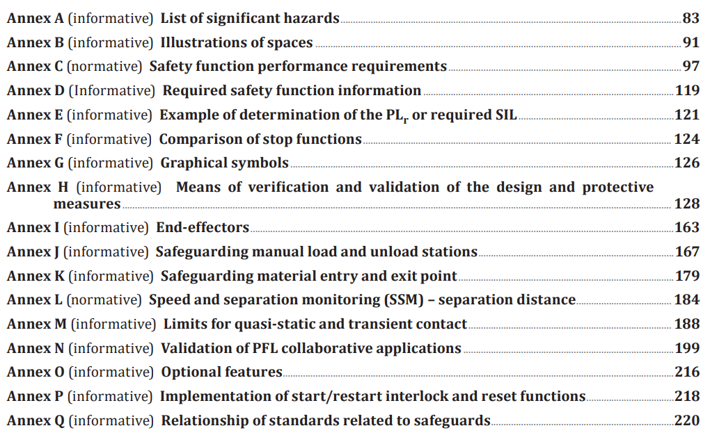
| Annex | Type | Summary |
|---|---|---|
| A List of significant hazards |
Normative→Informative | Status changed — mandatory wording moved from normative to informative annex |
| B Illustrations of spaces |
Informative | Diagrams for maximum, restricted, operating, safeguarded and related space concepts |
| C Safety-function performance |
Normative | C.1 Determination of PLr/SIL + Table C.1 (trigger, intended outcome, default PLr/SIL per safety function); C.2 Risk-estimation parameters |
| D Required safety-function information |
Informative | Table D.1 template — how to document name, mode, trigger, intended outcome, PL/SIL, etc. |
| E PLr / SIL determination examples |
Informative | Examples for ISO 12100, IEC 62061 and RIA TR R15.306; terminology comparison |
| F Stop functions compared |
Informative | Table F.1 — six stop functions: purpose, stop category, reset conditions |
| G Graphical symbols |
Informative | Guidance on symbols for emergency stop, automatic/manual mode, etc. |
| H Means of verification |
Normative→Informative | Clause-by-clause verification/validation for Clause 5 (Table H.1, ten methods) — moved from former Annex G |
| I End-effectors |
Informative | Design notes for gripping, vacuum, magnetic types; safety functions; collaborative examples |
| J Manual load/unload safeguarding |
Informative | Figures J.1–J.9 — access prevention, height of impediment devices, presence/intrusion detection, multi-zone sequencing |
| K Material opening safeguarding |
Informative | Material transfer openings — small openings (≤180 mm), tunnels, ESPE (Figures K.1–K.4) |
| L SSM separation distance |
Normative | Formula Sp = Sh + Sr + Ss + C + Zd + Zr and calculation of each term |
| M Quasi-static / transient limits |
Informative | Table M.2 — force/pressure limits per body region (29 regions); Tables M.3–M.4 — effective mass, spring constants, energy transfer |
| N PFL verification |
Informative | PFL verification methodology — PFMD specification and calibration, measurement by contact type (Figure N.4), analysis and re-verification |
| O Optional capabilities |
Informative | Optional functions beyond minimum requirements — e.g. emergency-stop outputs, collision detection, path accuracy, monitored positions, stop-performance monitoring |
| P Start/restart interlocking and reset |
Informative | Interlocks for energy restoration, mode change, unexpected start after stop; reset procedure (Figure P.1) |
| Q Relationship of safeguarding standards |
Informative | Diagram relating ISO 13849, ISO 14119, ISO 14120, IEC 61496, etc. |
5. Integration of ISO/TS 15066 (HGC / SSM / PFL)
Previously, collaborative-application safety often had to be read alongside ISO/TS 15066. In ISO 10218-2:2025, much of that content is now addressed within the standard itself, across Clause 5 and Annexes L, M and N, so the main requirements and supporting guidance for HGC, SSM and PFL are easier to review together.
The operator manually guides the robot arm
5.14.4 specifies detailed requirements for guiding-device design and use
Maintains separation distance in real time from operator position
5.14.5 + normative Annex L define the separation-distance formula
Verify that contact forces and pressures do not exceed body-region limits
5.14.6 + Annexes M and N define quasi-static vs transient contact and limit values
SSM separation distance (Annex L — normative)
| Symbol | Meaning | Calculation |
|---|---|---|
| Sh | Contribution from change in operator position | ∫(t0 → t0+Tr+Ts) vh(t) dt or 1.6 × (Tr + Ts) |
| Sr | Contribution from robot-application reaction time (e.g. sensor latency) | vr × Tr |
| Ss | Contribution while the robot application comes to a stop | ∫(t0+Tr → t0+Tr+Ts) vs(t) dt |
| C | Intrusion distance — possible penetration of the body beyond the detection zone (per ISO 13855) | Per safeguarding device data and ISO 13855 |
| Zd | Position uncertainty of the operator — measurement uncertainty of the presence-sensing device (PSD) | Per device manufacturer data sheet |
| Zr | Position uncertainty of the robot application | Per robot manufacturer data sheet |
PFL limit values and verification (Annexes M and N)
★ Practical requirements for PFL verification
This section summarises the standard requirements only.
Contact types
Quasi-static contact
A body segment can be clamped between moving parts of the robot application and fixed parts → stricter limit values
Transient contact
No clamping; the body can move away from moving parts after impact → for the applicable body regions listed in Table M.2, the standard presents transient limits using a multiplier value of 2 relative to the quasi-static values

Risk-assessment process for collaborative applications
Which body regions are exposed? Is contact part of the intended task or a reasonably foreseeable hazardous situation?
Which limits apply?
• Possible clamping → quasi-static limits
• Impact and rebound → transient limits
Reproduce contact conditions and measure with a PFMD, or where appropriate use the calculation method described in Annex M, M.3.4, supported as needed by computational analysis (e.g. simulation).
Compare measured or calculated values with body-region limits in Annex M
① Optimise speed (PFL + reduced-speed safety function)
② Improve end-effector geometry (radii, compliant covers)
③ Apply SSM (stop robot before contact using sensors)
④ Change layout (reduce contact likelihood or steer contacts toward body regions with higher permissible limits)
6. What robot end-users need to know
Items in the 2025 edition that most directly affect operating companies, focused on what to verify when using or procuring robots.
⚠️ Important: risk-assessment unit
The previous edition often centred risk assessment on the robot; ISO 10218-2:2025 requires assessment of the robot application and robot cell (= robot system + workpiece + robot program + linked automation machinery).
For existing cells, it is good practice to review whether risk assessment still aligns with the revised standard.
① Review your risk-assessment approach
If assessments were done for the “robot system” only, update them to cover the full robot application or robot cell, including workpiece, program and related machinery.
Clause 4.1Confirm all 22 task types in 4.2 are considered (commissioning, access to safeguarded space, application changes, relocation, decommissioning, etc.)—not only the previous ten.
Clause 4.2 e)ISO 10218-2:2025 states that the integrator should seek participation of the user when conducting the risk assessment. In practice, that usually means involving relevant user-side personnel such as operators and maintenance staff and keeping records of that input.
Clause 4.1Clause 4.1 requires risk assessment using ISO 12100 (general principles for machinery safety). Make the standards and methodology used in the risk assessment explicit in the documentation.
Clause 4.1② Collaborative applications (PFL / SSM / HGC)
For every foreseeable contact during collaborative tasks, classify as quasi-static (clamping) or transient (rebound)—limit values differ.
4.3.2 · Annex MCompare measured or calculated forces and pressures with Annex M, Table M.2. Use a PFMD, or where appropriate apply the calculation method described in Annex M, M.3.4, supported as needed by computational analysis (e.g. simulation).
5.14.6 · Annexes M, NCalculate Sp = Sh + Sr + Ss + C + Zd + Zr. Revisit any rule-of-thumb distances using robot speeds and sensor uncertainty.
5.14.5 · Annex LInstructions shall include collaborative safety-function types (HGC/SSM/PFL), separation distances (SSM), and force/pressure limits (PFL) as required.
7.5.22③ Cybersecurity and safety-function management
Carry out 5.2.16 for the robot control system: network exposure, remote access, supplier remote maintenance, etc.
5.2.16 (new)Define who may change safety parameters; manage change logs; require restart or re-initialisation after changes per 5.5.5.
5.5.5 (new)Can the whole safeguarded space be checked visually before restart? If not, provide presence-sensing, sequential reset, or one of the alternatives in 5.8.10.
5.8.10 (new)Ensure emergency stop, protective stop and normal stop are clearly separated. Check that emergency-stop devices are not used for routine stopping (explicitly prohibited in the 2025 edition).
5.6.2–5.6.4End-user checklist
📋 Risk assessment
- Assessment unit is the robot application or robot cell
- Shop-floor workers participate in the assessment
🤝 Collaborative applications (PFL / SSM)
- Assess contact events by body region, cause, likelihood and contact type
- Always distinguish quasi-static (clamping) vs transient contact
🛡️ Security / stop functions
- Maintain cybersecurity assessments and internal governance
- If safety functions use networks, review 5.5.9 / IEC 61508-2 7.4.11
- Do not use emergency-stop devices as normal-stop devices
📄 Documentation
- Include cybersecurity and collaborative-application information (HGC/SSM/PFL) in information for use
- Update risk assessment after changes; record dates and train workers accordingly
- Record all participants (including workers) in assessment documentation
7. What system integrators need to know
Key integration tasks by project phase.
Risk assessment
- Set the assessment unit to robot application or robot cell—including workpiece, program and related machinery
- Assess all 22 task types in 4.2
- For collaborative applications, apply layout requirements in 5.4.4
Functional safety
- Select PLr or SIL for each safety function from Annex C, Table C.1, or derive it using the risk-estimation parameters in Annex C and the example method in Annex E (severity, exposure, probability of occurrence, possibility of avoidance)
- Where PL d is required: Category 3 architecture or PFH < 4.43×10⁻⁷/h
- Safety-function parameter protection (5.5.5)—access rights, change logs, re-initialisation
Additional axes (5.2.9)
- Apply 5.2.1, 5.2.2, 5.2.8, 5.5, 5.6 and 5.7 to additional axes as well
- If an additional axis affects TCP speed in reduced-speed manual mode, apply 5.5.6.1
- Provide safeguarding where synchronised additional axes can create speed-difference hazards
Other
- End-effector (5.9)—geometry, surfaces, force sensing, gripping, tool changers
- Cybersecurity threat assessment (5.2.16) and unauthorised-access measures
- Vertical lifting elements (5.10)
- Commissioning plan and procedures (5.15)
- Implement and verify emergency stop, protective stop and normal stop
- Unexpected-restart prevention (5.8.10)
- Monitored-speed safety function for high-speed manual mode (5.5.6.2)
- Remote control per 5.7.6.3 where applicable
- Muting per IEC 62046:2018
- Manual load/unload stations (5.12.2)
- Adjacent robot cells (5.13)
Verification
- PFL—verify forces and pressures by PFMD or by the Annex M, M.3.4 calculation method where applicable
- SSM—calculate and verify Sp using Annex L
Documentation (23 items in 7.5)
- Safety-function information (7.5.16)—types, PLr/SIL, PFH, architecture
- Collaborative-application information (7.5.22)—HGC/SSM/PFL
- End-effector (7.5.20), restricted spaces (7.5.13), cybersecurity (7.5.23)
- Complete instructions for all items 7.5.1–7.5.23
Functional safety—two ways to set PLr / SIL
Route ① Pick from Table C.1
- Confirm the safety function appears in Table C.1
- Use the default PLr / SIL given there
- Design the SRP/CS to achieve that level
Route ② Derive from risk assessment
- Severity (Se), frequency/exposure (Fr)
- Probability of occurrence (Pr), possibility of avoidance (Av)
- Probability of injury (DL)—new parameter in the 2025 edition
| Item | Category 3 + PL d | Category 2 + PL d | PFH route |
|---|---|---|---|
| Architecture | Dual channel + cross-monitoring—fault tolerance | Single channel + test channel—high DCavg | Any architecture if PFH target is met |
| 2025 edition | Permitted route | DCavg > 90% & MTTFD > 62 years | PFH < 4.43×10⁻⁷/h |
| 2011 edition | Permitted (only route stated) | Not stated | Not stated |
Integrator checklist
🛠️ Functional safety
- Set PLr/SIL from Annex C or from risk assessment
- For PL d—Category 3 or PFH < 4.43×10⁻⁷/h
- For Category 2 to PL d—verify DCavg > 90% and MTTFD > 62 years
- Where protective stop uses stop category 2 to maintain position, assess the need for monitored standstill
- Safety parameters: authorised persons only, checksums, restart after changes
- Data communication for safety functions—IEC 61508-2 7.4.11
🤝 Collaborative applications / end-effectors
- Use “collaborative application” and “collaborative task”—not “collaborative robot”
- PFL—measure/calculate forces and pressures vs Annexes M and N
- SSM—Sp = Sh + Sr + Ss + C + Zd + Zr (Annex L)
- HGC—verify guiding-device design (5.14.4)
- End-effectors—manual release without power where trapping is possible; round edges or energy-absorbing materials
⚙️ Equipment / control
- High-speed manual mode—monitored speed (5.5.6.2) + enabling device on teach pendant
- Remote control—local acknowledgement for remote mode changes
- Additional axes—apply 5.5.6.1 when they affect TCP speed in reduced-speed manual mode
- Block automatic robot motion while additional axes run at non-reduced speed
📋 Documentation
- Commissioning plan, instructions for use, maintenance procedures
- Document each safety function—type, PLr/SIL, PFH, architecture—for the robot application
8. Shared priorities for end-users and integrators
Include workpiece, program and related machinery. Review legacy reports that stopped at the robot system.
HGC, SSM and PFL—methods, limits and verification—are now addressed directly within ISO 10218-2:2025, across Clause 5 and Annexes L, M and N.
Annex C supports differentiated levels; Category 2 can reach PL d under stated conditions.
If threats can affect safety, apply unauthorised-access measures; document cybersecurity in information for use.
Normal stop is formalised in 5.6.4. Emergency-stop devices must not be used for routine stopping.
Typically needed where stop category 2 is used to maintain position with drive power active and unintended motion has to be prevented.
The same robot can run collaborative or non-collaborative applications. Verification targets the application, not the robot model alone. The term “collaborative robot” is removed; use “collaborative application” and “collaborative task”.
Further items to verify
Beyond the headlines, these clauses often affect real layouts and documentation.
📌 ① Standard title
Use the current international English title, Robotics — Safety requirements — Part 2: Industrial robot applications and robot cells, in declarations, contracts and technical files. Cite the edition you rely on.
👥 ② Interested parties (Introduction)
The Introduction explicitly names robot manufacturers, robot application integrators, health and safety bodies, robot application users/employers, robot application users/employees, and service providers as relevant stakeholder groups. In 4.1, the integrator is also expected to seek participation of the user when conducting the risk assessment.
🗺️ ③ Layout and non-collaborative traffic (4.2 f) (new)
New requirement: movement of workers not involved in the collaborative application can pass through the collaborative safeguarded space, so layout design shall account for this.
Risk assessment and safeguarding should also consider adjacent task zones and people whose travel paths cross the collaborative safeguarded space—not only the operators performing the collaborative task.
📡 ④ Safety-related data communication (5.5.9, new)
When safety functions use networks, required measures depend on exposure (IEC 61508-2 7.4.11).
- Category 1 — known and fixed participants: transmission properties are known and invariable during the lifetime of the system; negligible opportunity for unauthorized access
- Category 2 — known user group(s): some properties can be variable; user-group extension is limited; opportunity for unauthorized access remains negligible
- Category 3 — unknown or multiple user groups: system properties can be unknown or variable; there is significant opportunity for unauthorized access
If the robot safety network is not confined to an internal fixed network, assess it against category 2 or 3 characteristics and address corruption, delay, loss and unauthorized access.
Turn a complex revision into structured workflows in the browser.
From questionnaire-based risk assessment to PFL contact analysis and standard-aligned report generation.
This page is a reference guide based on ISO 10218-2:2025 and related documents including ISO 10218-1:2025, ISO/TS 15066:2016 and ISO 12100.
For actual robot cells, review the original standards for detailed safety specifications and evidence requirements, and confirm certification or inspection expectations with the relevant bodies in advance.
This English page follows the international ISO edition; national adoptions may differ in editorial detail or timing—check the edition cited in your jurisdiction.