
- 1. 3D Screen Layout
- 2. Detailed Screen Layout
- 2-1. Left Panel Layout
- ① Library
- ② Layer
- 2-2-1. Category Menu (Manipulator)
- ① Robot Information
- ② Gripper
- ③ Motion Settings
- ④ Collision Points
- ⑤ Collaborative Workspace
- ⑥ Analysis Options
- 2-2-2. Category Menu (Mobile Robot)
- ① Robot Information
- ② Path Settings
- ③ Collaborative Workspace
- ④ Analysis Options
- 2-2-3. Category Menu (Additional Axis)
- ① Additional Axis Information
- ② Path Settings
1. 3D Screen Layout
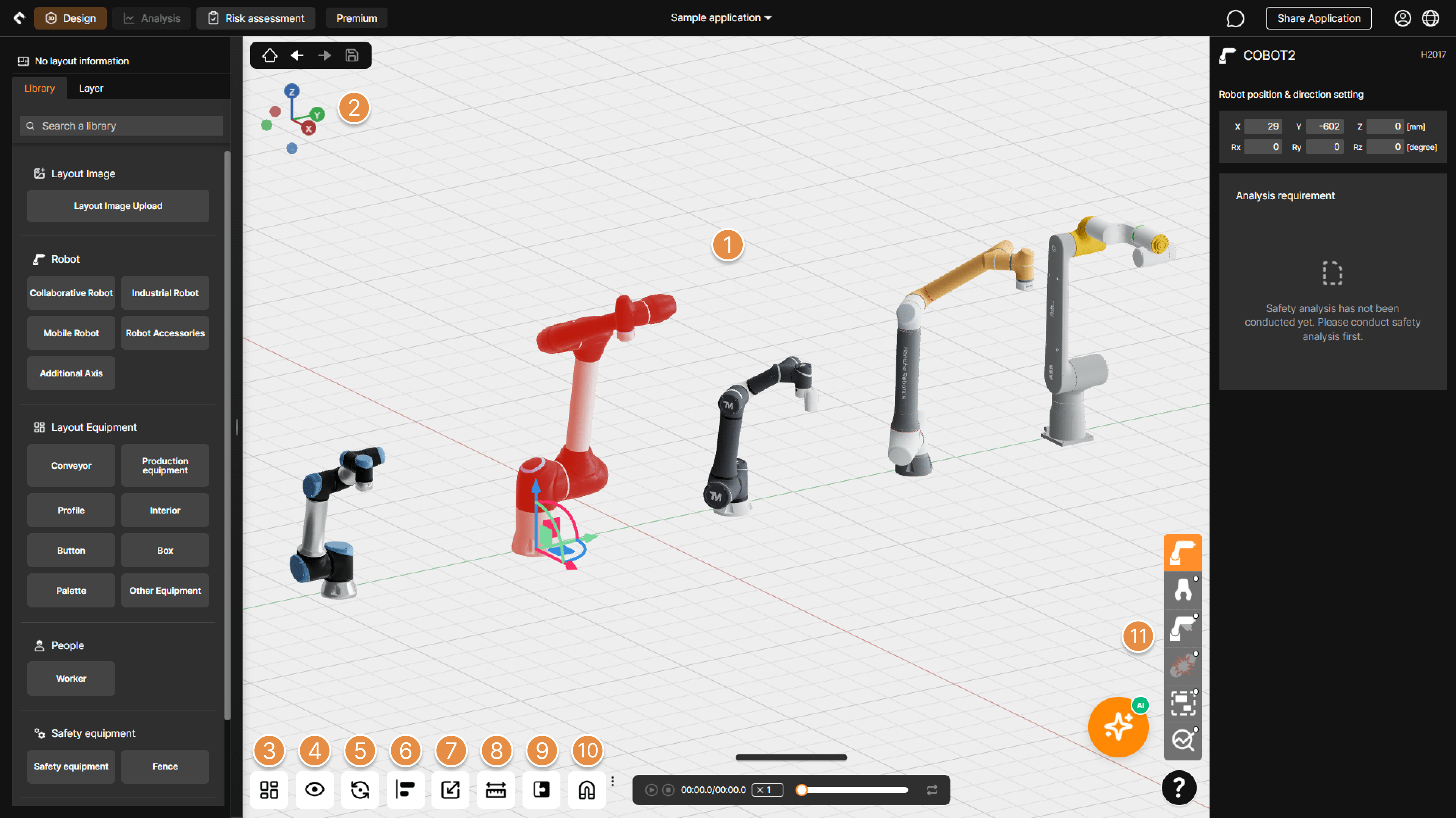
3D Screen Layout
① 3D Screen Controls
– Select Object : Click the left mouse button to select elements on the 3D screen.
Tip
Objects include robots, grippers, expected collision points, equipment, created motion waypoints, and collaborative workspaces.
– Pan : Hold the right mouse button and move the mouse to pan the view.
– Rotate : Hold the mouse wheel button and move the mouse to rotate the view.
– Zoom In / Out : Scroll the mouse wheel to zoom in or out based on the center of the screen.
② Quick View
Select one of six views (Top, Bottom, Left, Right, Front, Back) to view the screen.
③ Grid Size / Background Color Settings
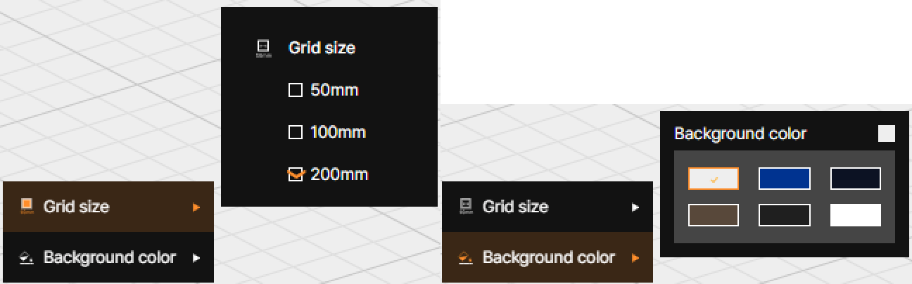
Adjust the grid spacing from three options (50mm, 100mm, 200mm) or customize the background color of the 3D screen to your preference.
④ View Mode
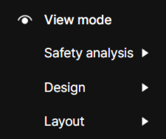
You can show or hide elements on the 3D screen by category: Safety Analysis, Design, and Layout.
⑤ Rotation Point Settings
Select a reference point for screen rotation when controlling the 3D screen.
⑥ Object Alignment
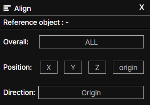
Among the elements placed on the 3D screen, align the subsequently selected object (selected by Ctrl+clicking) to match the coordinate position or facing direction of the initially selected object (reference object) using All alignment (ALL), Position alignment (X, Y, Z, Origin), or Direction alignment (Origin).
⑦ Scale
Click the Scale button to adjust the size of equipment placed on the 3D screen by mouse dragging. Click and hold the left mouse button on the point at the end of the arrow, then drag to increase or decrease the size in that direction.
⑧ Distance Calculation (Measurement)
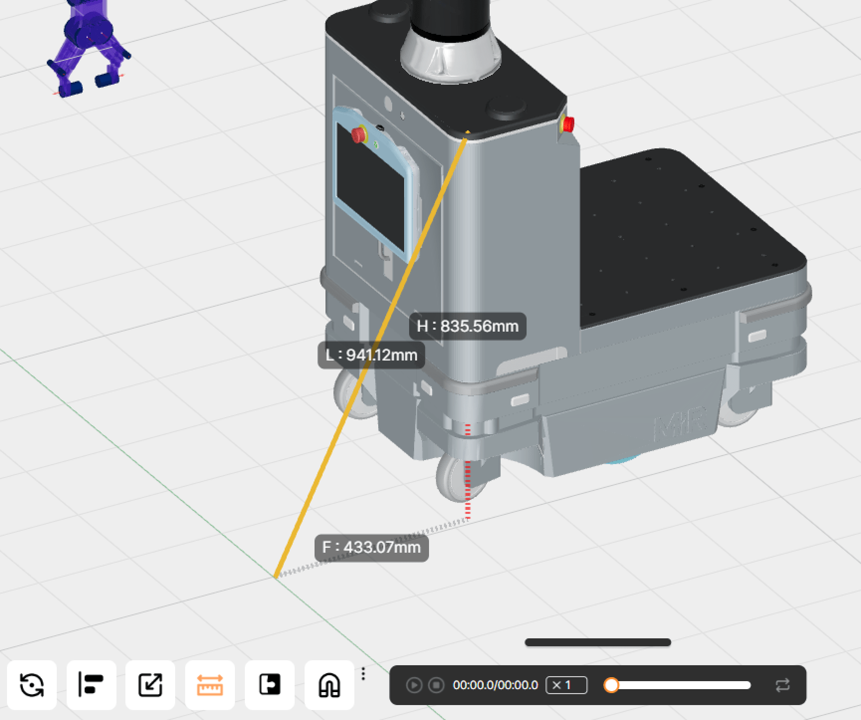
With the Distance Calculation feature enabled, click two points to measure the distance between them.
⑨ Snap Settings
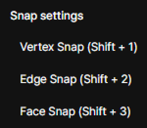
Use the Vertex Snap (Shift + 1), Edge Snap (Shift + 2), and Face Snap (Shift + 3) functions to precisely snap two objects together by their vertices, edges, or faces.
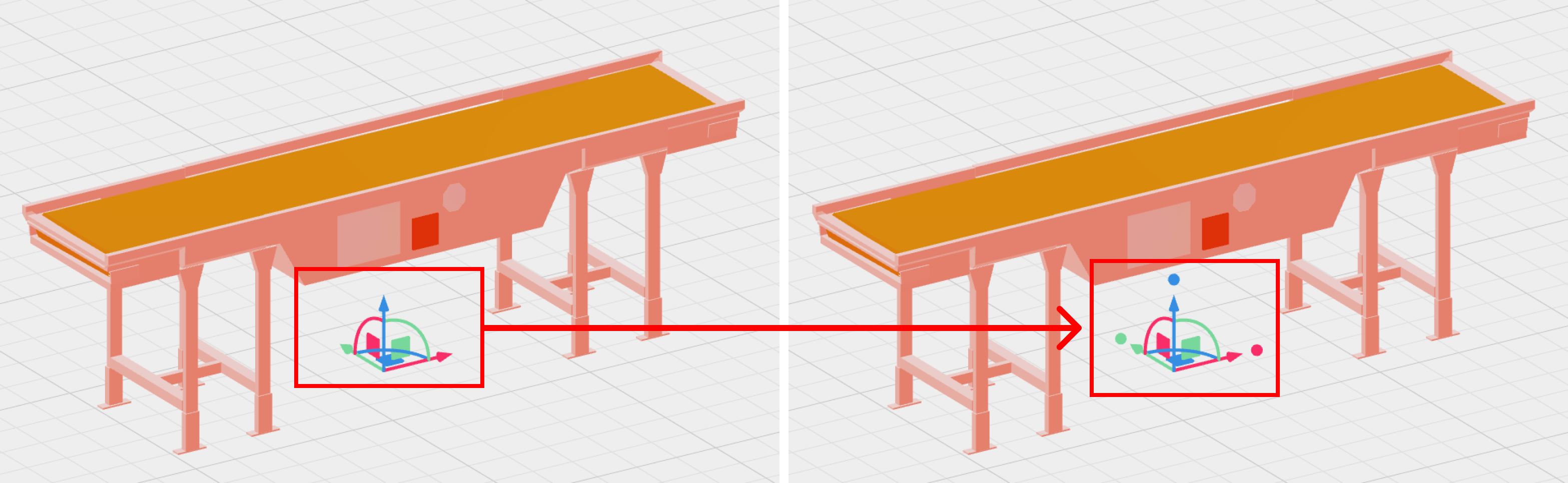
⑩ Snap Move/Rotate Settings
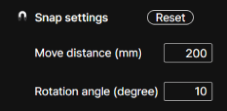
Set the movement distance (mm) and rotation angle (degree) increments for when dragging or rotating objects using the pivot controller (red, blue, green arrows), allowing consistent movement or rotation in fixed steps.
⑪ Category Menu
Enter information required for analysis or configure options related to running the analysis.
Top Bar – Right Menu
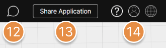
⑫ Comments
Comment Button Active State
View comments written by other users within the application, or write new comments.
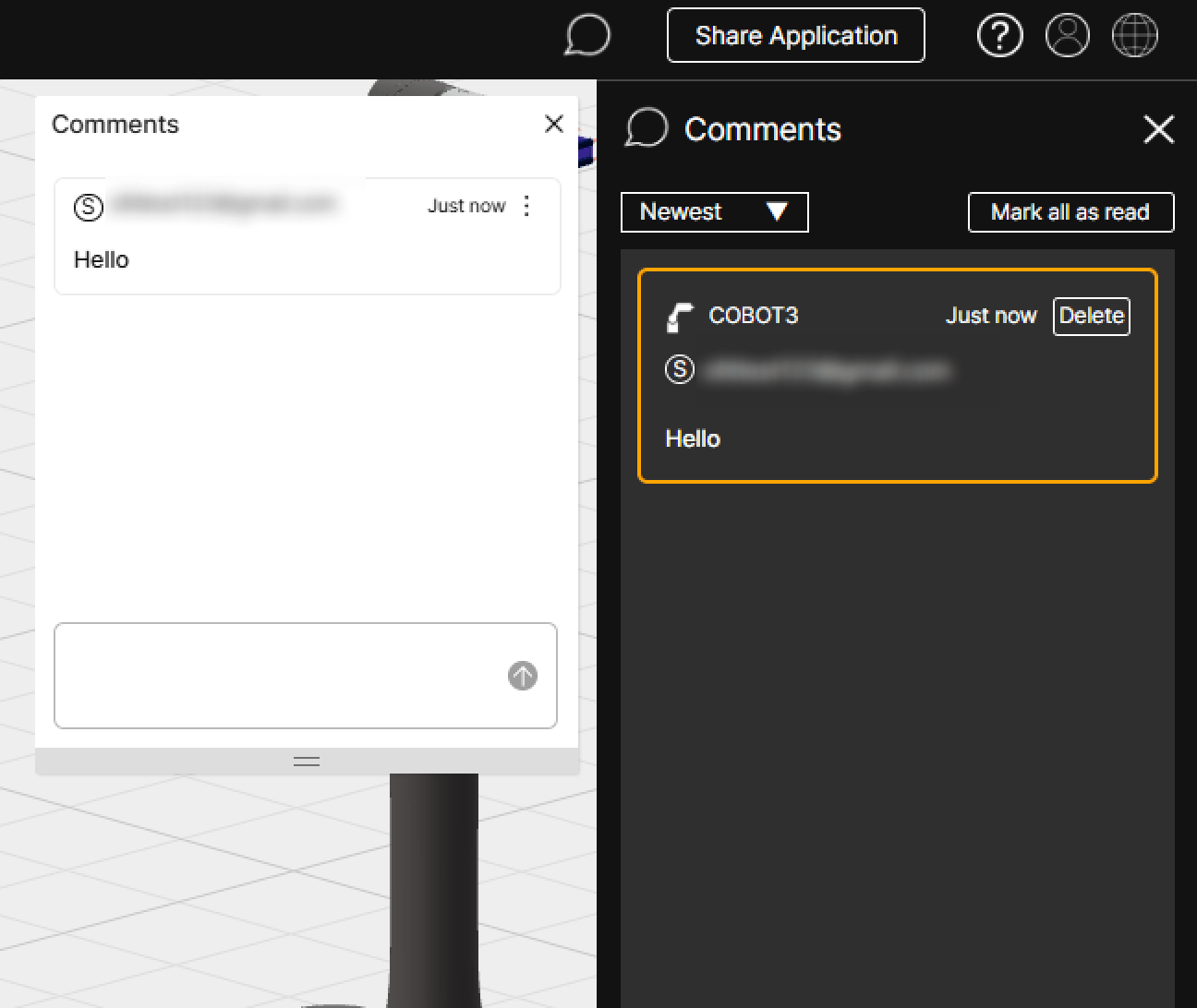
⑬ Share Application
Share the open application with other users via an email link.
Tip
For detailed instructions on how to use the Share Application feature, please refer to Application Share.
⑭ Profile / Language
– Profile Menu : Access the account information page, report issuance status page, or log out of SafetyDesigner.
– Language : Change the language of SafetyDesigner. (한국어(한국) / English(US))
2. Detailed Screen Layout
2-1. Left Panel Layout
3D Screen Detailed Layout
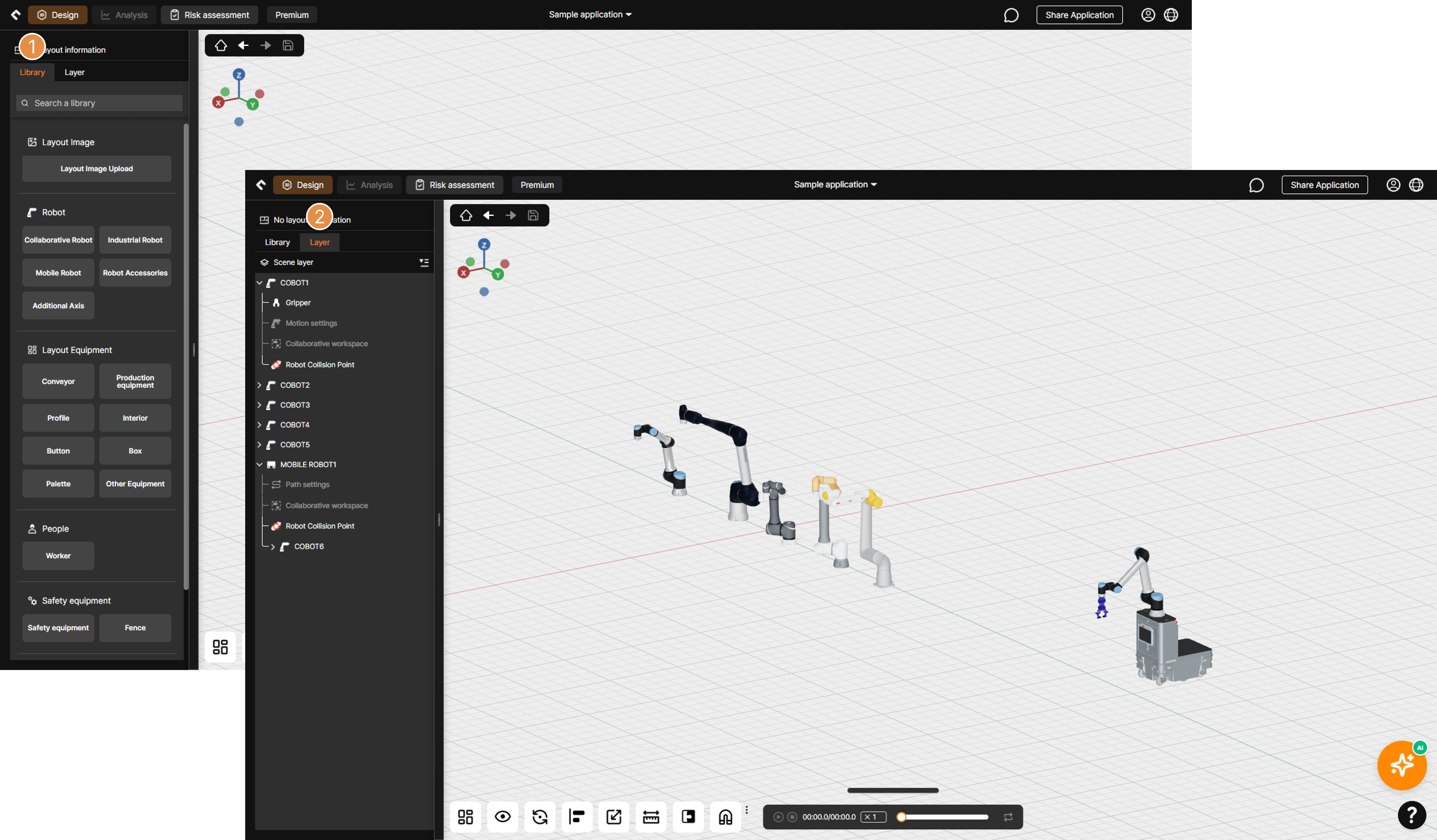
① Library
Select robots and surrounding equipment to place on the 3D screen, or upload 2D floor plan images.
② Layer
View the list of floor plans, robots, and equipment placed on the 3D screen, as well as the analysis-related information configured for robots.
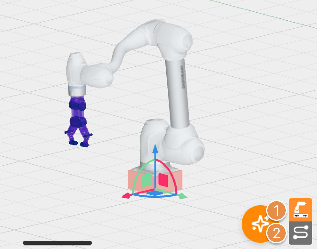
2-2-1. Category Menu (Manipulator)
① Robot Information
Configure robot placement information and rotation angles.
② Gripper
Select a gripper model from the library for analysis, or upload a custom gripper file (3D CAD).
③ Motion Settings
Upload actual motion extracted from the robot or use the Create Motion feature to enter robot motion information.
Tip
For instructions on how to use the Create Motion feature, please refer to What is Create Motion?
Tip
For detailed information about motion extraction, please refer to Using the Motion Extraction Program.
④ Collision Points
Specify collision points for analysis on the 3D models of the gripper and workpiece.
Tip
For detailed information about collision points, please refer to What is Collision Point? on the Advanced Tips.
⑤ Collaborative Workspace
Define a 2D collaborative workspace for the collision safety analysis.
⑥ Analysis Options
Configure options related to the analysis results and run the simulation.
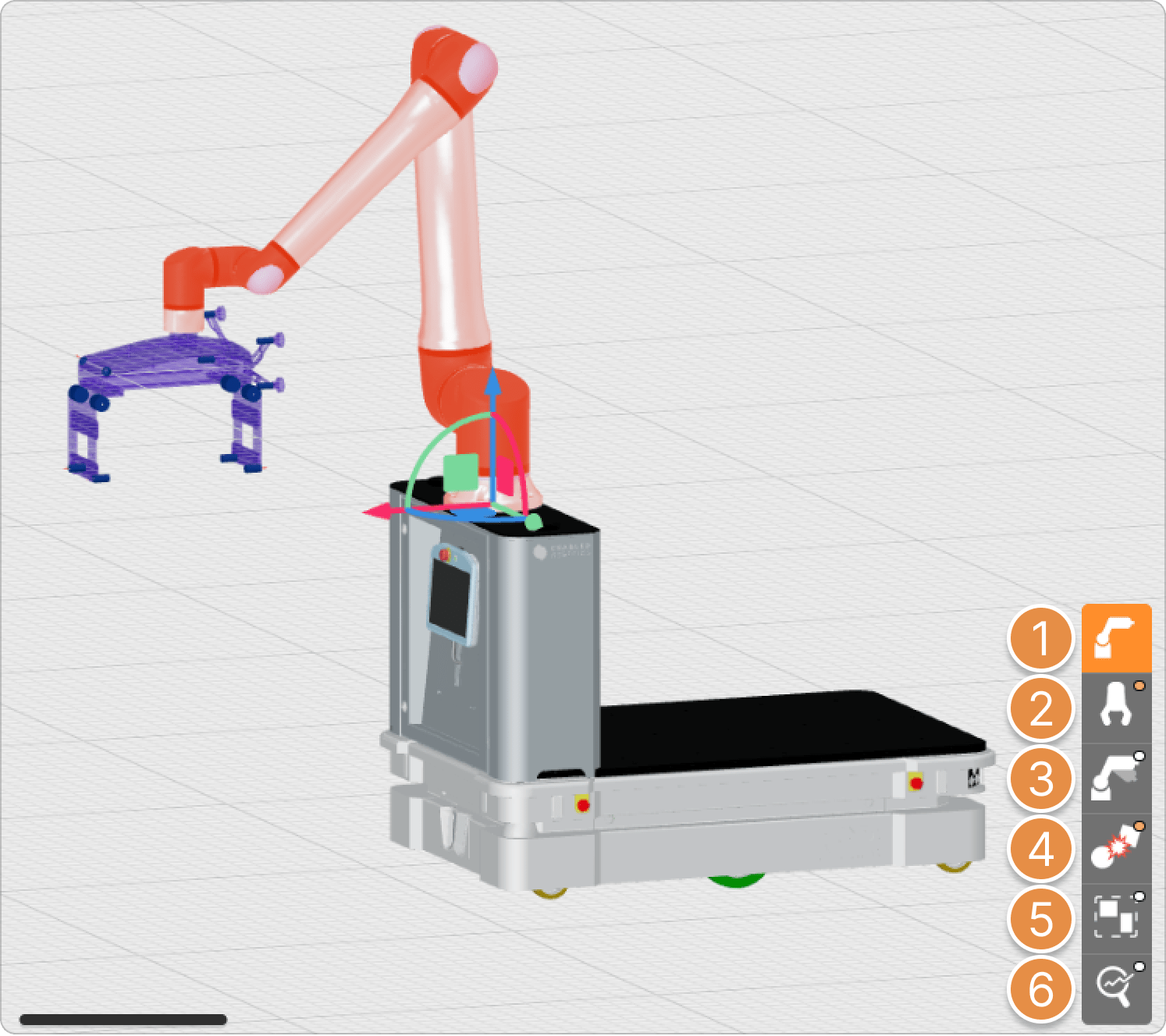
2-2-2. Category Menu (Mobile Robot)
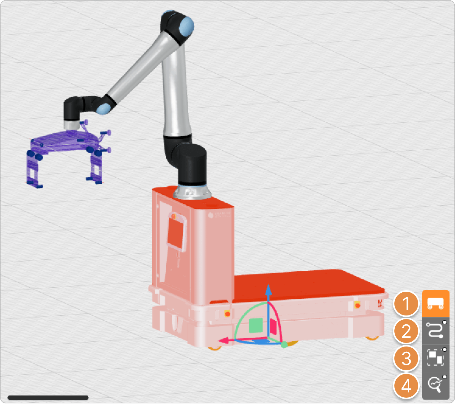
① Robot Information
Configure robot placement information and rotation angles.
② Path Settings
Use the Path Point settings feature to configure the movement path of the mobile robot for analysis. Mobile robots do not support motion extraction or motion upload features.
③ Collaborative Workspace
Define a 2D collaborative workspace for the collision safety analysis.
④ Analysis Options
Configure options related to the analysis results and run the simulation.
2-2-3. Category Menu (Additional Axis)
① Additional Axis Information
Configure placement information and rotation angles for the additional axis.
② Path Settings
Use the path settings feature to configure the movement path of the additional axis for analysis. The additional axis does not support motion extraction or motion upload features, and unlike mobile robot path creation, it also allows designing vertical movement motions (robot ascent/descent).