
Input layout information such as the equipment applied to the robot system and the robot’s location. The entered layout information is attached to the risk assessment report as an image.
The following section explains the detailed composition of the layout input screen and the two methods for entering layout information.
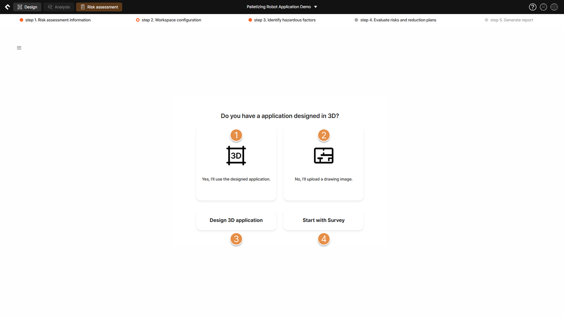
Step 2 – Workspace configuration input 1
Selecting a Layout Input Method
① Using 3D Application of SafetyDesigner
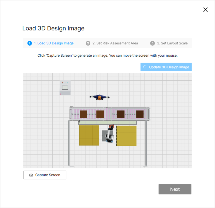
Load 3D application from SafetyDesigner
For a robot system that has undergone risk assessment, if a 3D application design created in SafetyDesigner is available, you can capture the designed 3D application in Top View for use instead of uploading a drawing image.
② Upload Drawing Image
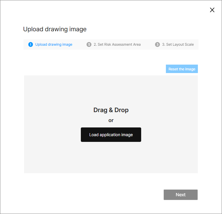
Upload drawing image
If no 3D application design created in SafetyDesigner is available, you can upload a drawing image for layout information input. The drawing image must be a jpg or png file under 10MB.
③ Design 3D Application
Navigate to the SafetyDesigner 3D screen.
④ Start with Survey
If no 3D application design has been performed in SafetyDesigner or a 2D drawing is not available, click this button to skip this step and proceed with Step 3. Identify hazardous factors and Step 4. Evaluate risks and reduction plans.
1. Load 3D Design Image or Upload Drawing Image
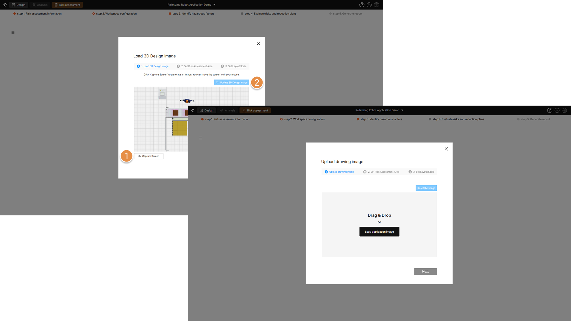
Load 3D design image or upload drawing image 1
① Capture Screen / Load application Image
(When using the 3D application created in SafetyDesigner) Capture the Top View of the 3D application displayed on the screen and use it for layout input.
② Update 3D Design Image
(When using the 3D application created in SafetyDesigner) If modifications have been made on the 3D screen, click the button to update the captured layout image.
2. Set Risk Assessment Area
Specify which area of the captured Top View image will be used for workspace configuration.
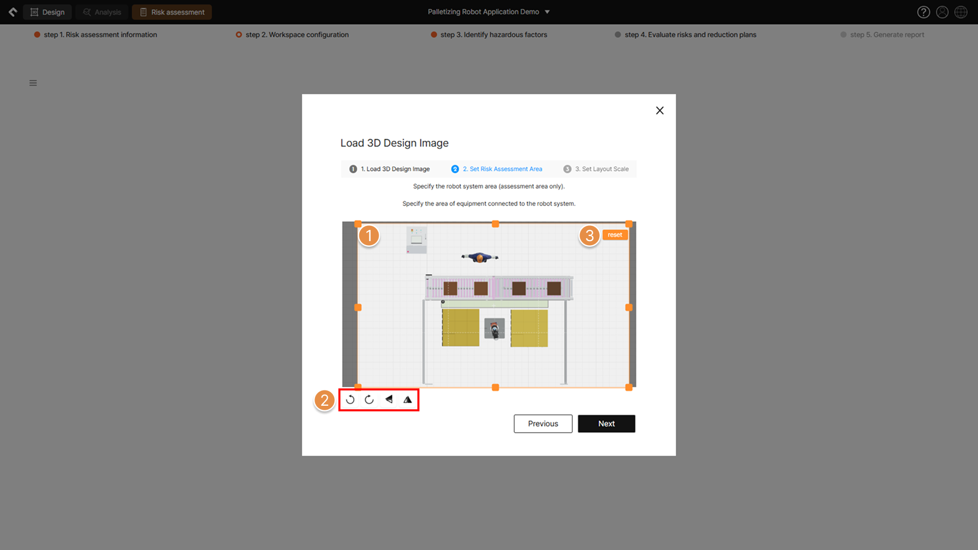
Load 3D design image or upload drawing image 2
① Specify Area
Designate the area from the captured image to use. Click and drag the orange dot to adjust or move the rectangular selection to your desired size.
② Orientation Adjustment
Rotate the captured layout image by 90° or flip it vertically/horizontally.
③ Reset
Reset all area selection and orientation adjustment settings.
3. Set Layout Scale
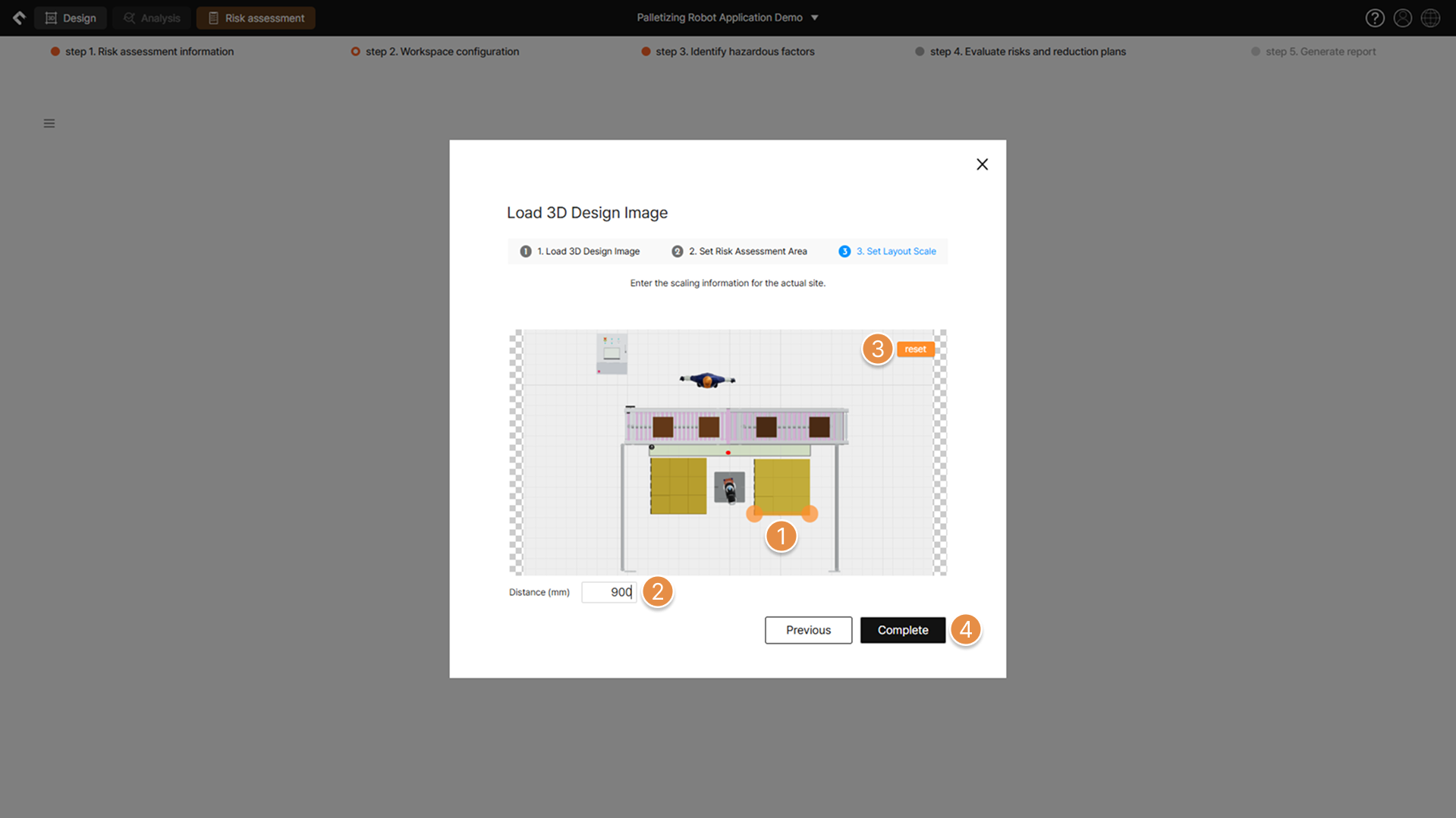
Load 3D design image or upload drawing image 3
① Set Positions
Select two points to define the distance. Click and drag the orange dots to move them to the desired positions.
② Enter Distance
Enter the distance between the two selected points.
③ Reset
Reset all entered values and position settings.
④ Complete
After specifying the area and entering scale information, click Complete button to move to the screen where you can enter safety space information on the layout image.
4. Safety Spaces Information
After uploading the layout image, enter the information related to the safety spaces of the robot system.
Tip
When conducting a risk assessment for robot systems, clearly indicate the robot’s safety spaces, as well as the locations of installed safety measures. For more information about safety spaces, see What are Safety Spaces? in the Handy Tips.
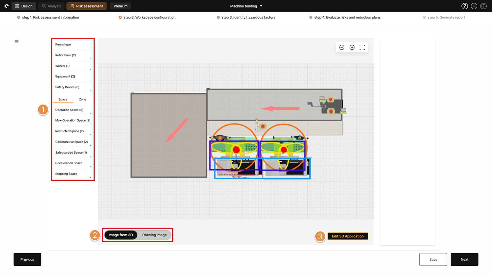
Workspace configuration – Robot system safety spaces
① Item List
Select items such as robot system safety spaces, worker positions, collaborative work areas shared by robots and workers, safety sensors, and emergency stop buttons, and place them onto the workspace on the layout image.
Hold down the Shift key while dragging to resize and place items proportionally.
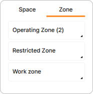
Space is used in the context of displaying information for collaborative and industrial robots; Zone is used in the context of displaying information for mobile robots.
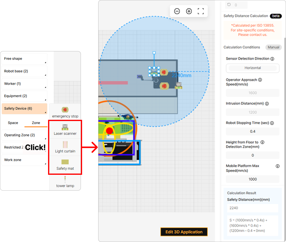
When a safety device such as a Laser scanner, Light curtain, or Safety mat is selected from the Safety Device list and placed on the drawing, clicking the placed device displays the Safety Distance Calculation panel on the right side of the screen. This panel functions as a calculator to determine the sensor’s safety distance.
② Image from 3D / Drawing image
Switch between the captured 3D application image and the uploaded drawing image for the layout.
③ Edit 3D Application / Edit 2D Drawing
Change or edit the captured 3D application image or the uploaded drawing image, and adjust the scale accordingly.
5. Restricted Space Information
Tip
For detailed information about configuring restricted space, see the Restricted Space section on the What are Safety Spaces? page.
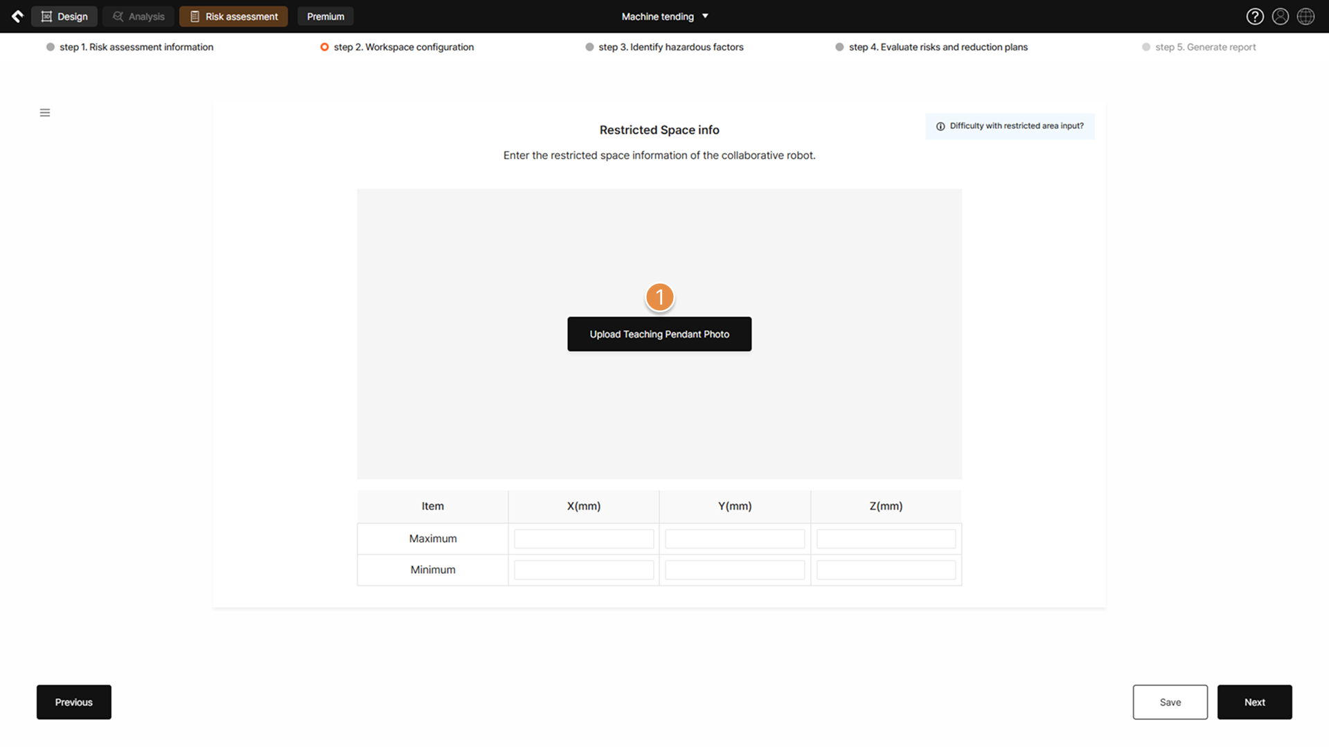
Workspace configuration – Restricted space
① Upload Teaching Pendant Photo
For detailed documentation of restricted space configuration, upload a captured image of the teaching pendant screen if the space is configured virtually, or attach photographs of physical devices such as limit switches or tension sensors if configured mechanically.