
1. 3D Screen Basic Elements
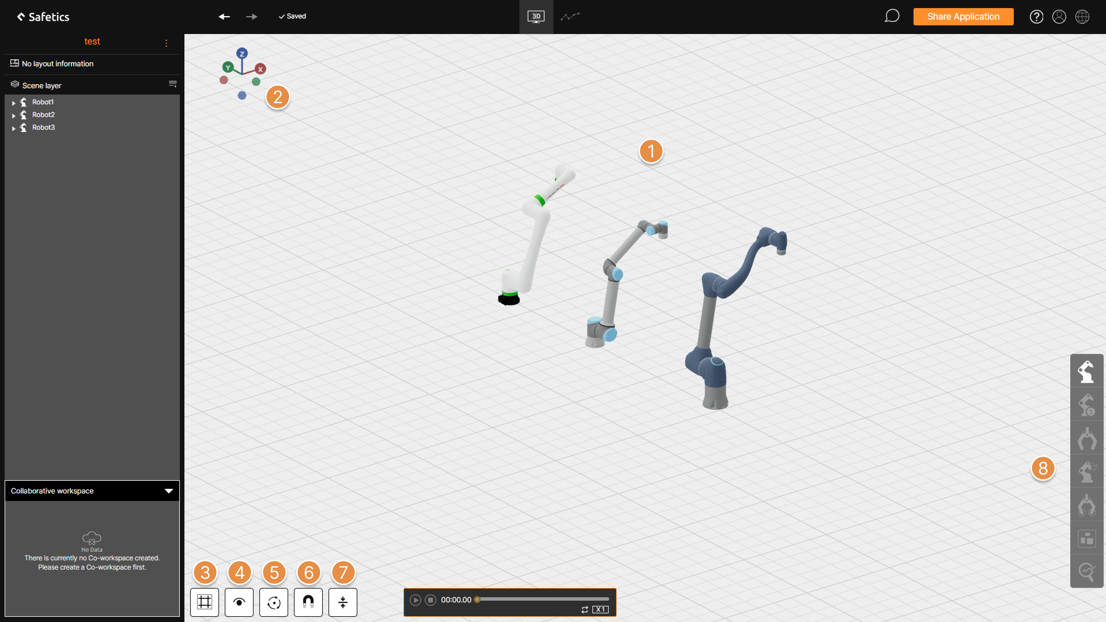
① Control 3D screen
– Select object : Click each of the Robot, Gripper, Collision point, Equipment, and Collaborative Workspace to modify or work on each objects.
 There are robot, gripper, collision point, 3d equipment, and collaborative workspace for selectable objects.
– Parallel move : Move Parallel when moving the mouse with the right mouse button pressed.
– Rotation : Rotate while pressing the mouse wheel button.
– Zoom / Zoom out : Rotate the mouse wheel button to zoom / zoom out the screen around the center of the 3D screen.
② Quick view
Check the screen by choosing from six views: up, down, left, right, front, and back.
③ Grid size / Background color setting
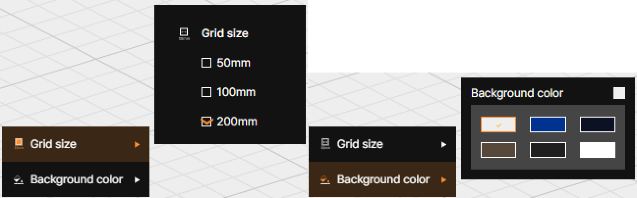
Adjust the grid size by selecting one of the three options (50mm, 100mm, 200mm), or set the background color of the 3D screen to your preference.
④ View mode
Set the objects to be displayed on the 3D screen to be visible or invisible using the checkbox.
⑤ Rotation point setting
Select the reference point to rotate the screen when operating the 3D screen.
⑥ Object alignment
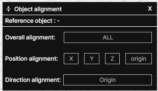
Align the X, Y, Z coordinates or rotation of objects in the 3D screen to match the reference object.
⑦ Scale
Adjust the size of the object placed on the 3D screen by dragging with the mouse. By clicking and holding the left mouse button on the point indicated at the end of the arrow, you can increase or decrease the size in that direction.
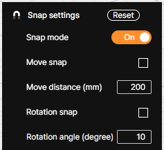
⑧ Snap settings
Set the 3D screen to move objects by the specified units in the X, Y, Z directions or rotate them by Rx, Ry, Rz.
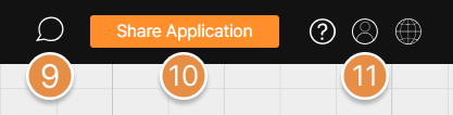
⑨ Category menu
Enter the information required for analysis or configure options related to running the analysis.
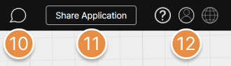
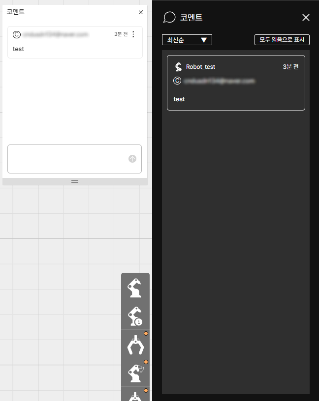
⑩ Comments
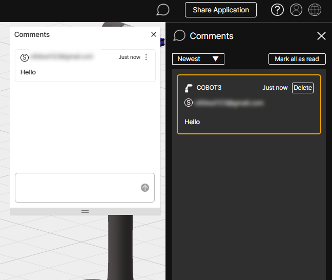
You can check the comments left on the application.
⑪ Share application
Share an application with another user via an email link.
For more information on how to use the application sharing feature, please refer to Application Sharing.
⑫ Profile Menu
Enter the account information page, analysis report issue status page, or log out from SafetyDesigner.
2. 3D Screen Detailed Elements
2-1. Left Panel
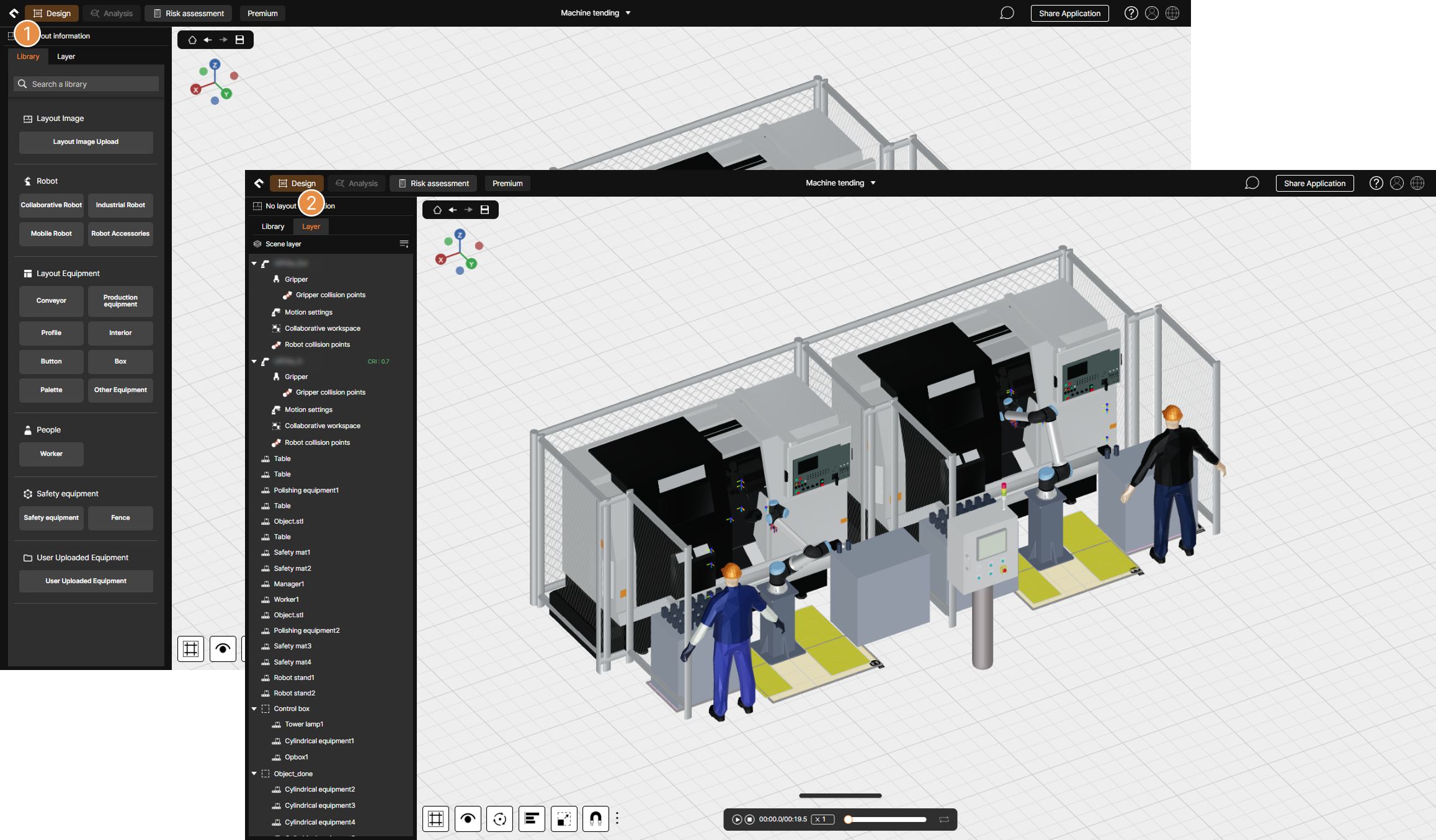
① Library
Placing robots and equipment on the 3D screen or uploading 2D layout images.
② Layer
Displays the list of 2D layout image, robots, and equipment placed on the 3D screen, and the list of analysis information configured for robots.
2-2-1. Category Menu (Collaborative Robots)
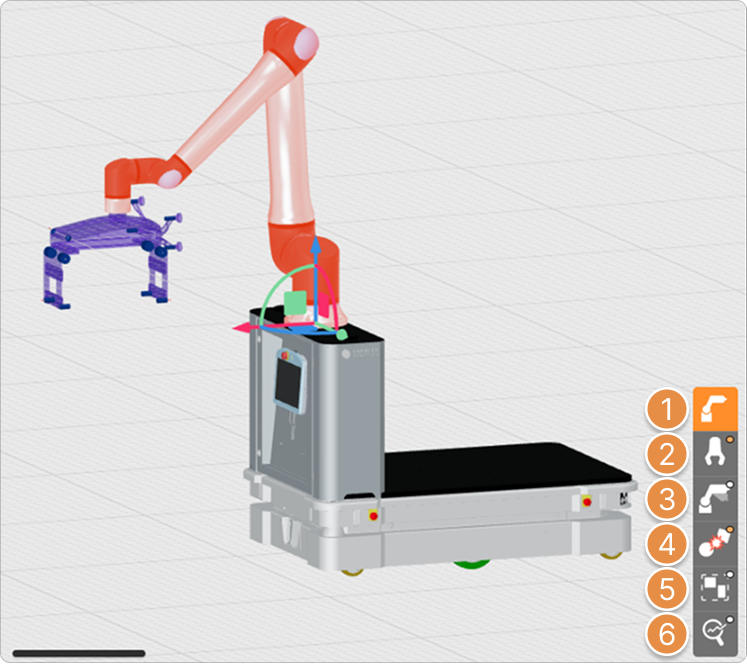
① Robot Information
Configure robot placement information, rotation angles, and other related settings.
② Gripper Settings
Select a gripper model from the library for analysis or upload a custom gripper file (3D CAD).
③ Motion Settings
Upload actual motions extracted from the robot or input robot motion information using the motion generation feature. For uploaded motions, use the motion segmentation feature to define robot parts to exclude from analysis and to set collision points.
For detailed instructions on using the motion generation and motion segmentation features, refer to What is Motion Create? and What is Motion Split?.
For detailed instructions on motion extraction, refer to Motion Extractor Program Guide.
④ Create Collision Point
Designate collision points on the 3D models of the gripper and workpiece where the analysis will be performed.
For more detailed information regarding collision point, refer to What is Collision Point?.
⑤ Collaborative Workspace
Define the 2D collaborative workspace where the collision risk analysis will be conducted.
⑥ Analysis Option
Configure options related to the analysis results and run the collision risk analysis.
2-2-2. Category Menu (Mobile Robots)
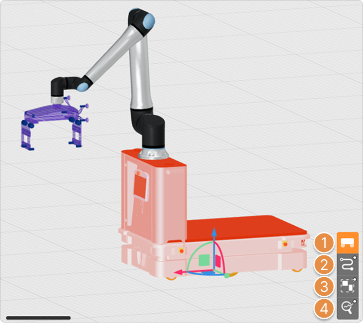
① Robot Information
Configure robot placement information, rotation angles, and other related settings.
② Path Point Settings
Draw the travel path for the mobile robot to be used in the analysis. Mobile robots do not support motion extraction and upload features.
③ Collaborative Workspace
Define the 2D collaborative workspace where the collision safety analysis will be conducted.
④ Analysis Option
Configure options related to the analysis results and run the collision safety analysis.